Healthy Climate® Dealer Filter Change Instructions
b.With each HEPA replacement filter, a new ‘o’ ring is provided. The old one is removed by pinching it between two fingers and pulling it off the collar on the blower deck.
c.Discard old ‘o’ ring.
d.Place the new ‘o’ ring onto the collar and slide it down to the base of the blower deck.
5. Optional Coconut Shell Carbon Canister
a.Remove old carbon canister (if installed) by pulling it out from the inside of the HEPA filter.
b.If replacing an inner charcoal filter with the carbon canister, remove inner charcoal filter by following the steps a. to c. in section 3.
c.Remove the plastic shrink wrap from the new carbon canister.
d.Slide the carbon canister into the HEPA cartridge, smaller, tapered end first. The carbon canister should slide all the way in until the metal edges at
the base meet the HEPA filter.
e.Support the carbon canister with your fingers so it does not slide out when replacing the HEPA cartridge assembly into the unit.
6. Installing the HEPA Filter Cartridge
a.With the filters changed or inspected, all 3 filters are ready to be placed back into the unit. Place the HEPA cartridge gently into the unit (if a carbon canister is being used, take care not to let it slide out as it is heavy and could damage the unit)
b.When the HEPA cartridge is in place, brace the unit, press down and turn it clockwise to lock it into place.
c.Replace the HEPA filter access panel and latch it with the four retaining clips.
d.
e.Plug the unit back into a power outlet and turn it on.
Healthy Climate® Dealer Motor Assembly Replacement Instructions
!WARNING
Electrical Shock Hazard.
Can cause injury or death.
Disconnect all electrical power supplies before servicing.
Do no operate equipment without access panels in place
Do not use this fan with any
!CAUTION
Risk of Sharp Edges Hazard.
Equipment sharp edges can cause injuries.
Avoid grasping equipment edges without protective gloves.
1. Accessing the motor assembly
a.Turn the unit off and unplug it from any electrical source before opening the cabinet.
b.To remove the motor section access panel, remove the four screws on the panel, and lift off panel.
2. Removing the old motor assembly
a.Disconnect all four motor wires from switch, ground post and capacitor.
b.Disconnect the two white wires from the capacitor.
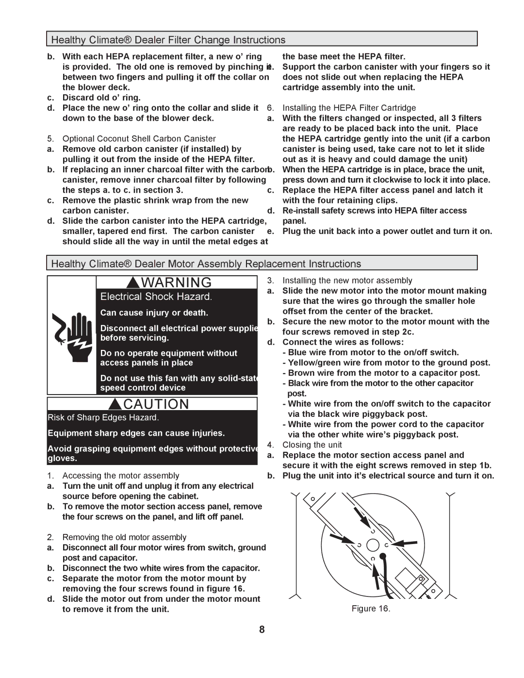
c.Separate the motor from the motor mount by removing the four screws found in figure 16.
d.Slide the motor out from under the motor mount to remove it from the unit.
3. Installing the new motor assembly
a.Slide the new motor into the motor mount making sure that the wires go through the smaller hole offset from the center of the bracket.
b.Secure the new motor to the motor mount with the four screws removed in step 2c.
d.Connect the wires as follows:
-Blue wire from motor to the on/off switch.
-Yellow/green wire from motor to the ground post.
-Brown wire from the motor to a capacitor post.
-Black wire from the motor to the other capacitor post.
-White wire from the on/off switch to the capacitor via the black wire piggyback post.
-White wire from the power cord to the capacitor via the other white wire’s piggyback post.
4. Closing the unit
a.Replace the motor section access panel and secure it with the eight screws removed in step 1b.
b.Plug the unit into it’s electrical source and turn it on.
Figure 16.