Lenovo G460e/G560e Hardware Maintenance Manual
1160 LCD panel, LCD cable and hinges
For access, remove these FRUs in order:
•“1010 Battery pack” on page 34
•“1020 Dummy card” on page 35
•“1030 Hard disk drive(HDD)/Memory/Mini PCI Express Card slot compartment cover” on page 36
•“1040 Hard disk drive” on page 37
•“1050 Optical drive” on page 39
•“1060 DIMM” on page 40
•“1070 PCI Express Mini Card for wireless LAN/WAN” on page 41
•“1080 Keyboard” on page 43
•“1100 Keyboard bezel” on page 48
•“1110 System board” on page 53
•“1120 LCD unit” on page 57
•“1150 LCD front bezel” on page 64
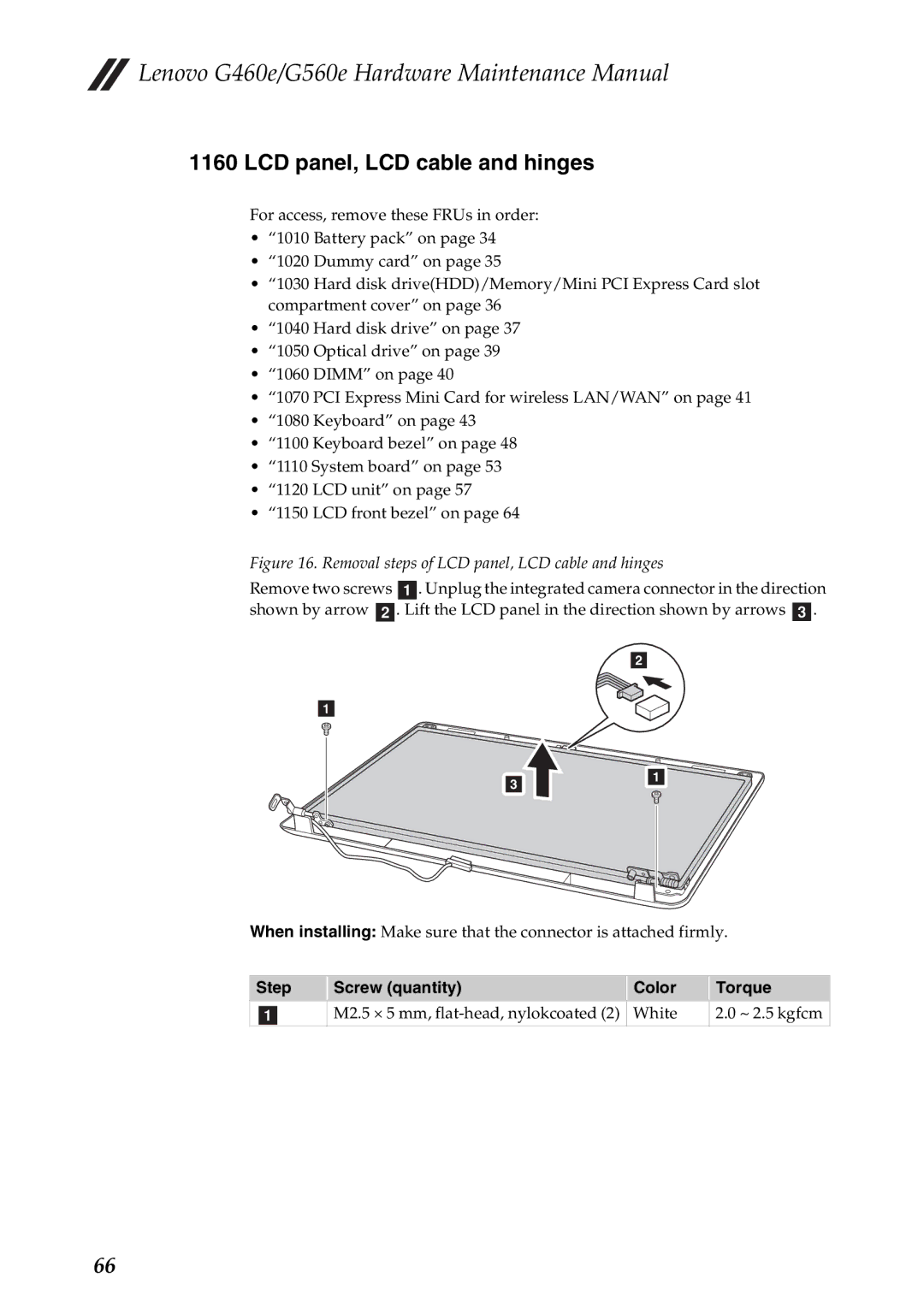
Figure 16. Removal steps of LCD panel, LCD cable and hinges
Remove two screws a. Unplug the integrated camera connector in the direction shown by arrow b. Lift the LCD panel in the direction shown by arrows c.
2
1
3
1
When installing: Make sure that the connector is attached firmly.
Step | Screw (quantity) | Color | Torque |
a | M2.5 × 5 mm, | White | 2.0 ~ 2.5 kgfcm |
66