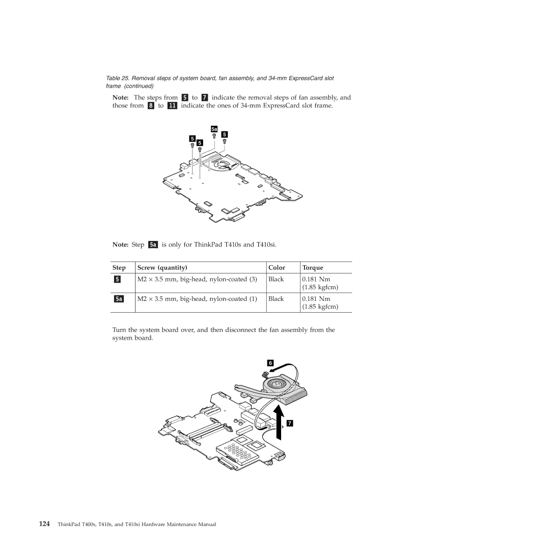
Table 25. Removal steps of system board, fan assembly, and
Note: The steps from |
| to |
| indicate the removal steps of fan assembly, and | ||||||
those from | to | indicate the ones of | ||||||||
|
|
|
|
|
|
|
|
|
|
|
|
|
|
|
|
|
|
|
|
|
|
|
|
|
|
|
|
|
|
|
|
|
|
|
|
|
|
|
|
|
|
|
|
|
|
|
|
|
|
|
|
|
|
|
|
|
|
|
|
|
|
|
|
|
|
|
|
|
|
|
|
|
|
|
|
|
Note: Step | is only for ThinkPad T410s and T410si. |
| ||
|
|
|
| |
Step | Screw (quantity) | Color | Torque | |
|
|
|
| |
| M2 ⋅ 3.5 mm, | Black | 0.181 Nm | |
|
|
|
| (1.85 kgfcm) |
|
|
|
| |
| M2 ⋅ 3.5 mm, | Black | 0.181 Nm | |
|
|
|
| (1.85 kgfcm) |
|
|
|
|
|
Turn the system board over, and then disconnect the fan assembly from the system board.
6
7
124ThinkPad T400s, T410s, and T410si Hardware Maintenance Manual
