IdeaPad Z360 Hardware Maintenance Manual
1170 LCD front bezel
For access, remove these FRUs in order:
•• “1010 Battery pack” on page 34
•• “1020 Dummy card” on page 35
•• “1030 Hard disk drive (HDD)/PCI Express Mini Card slot cover” on page 36
•• “1040 Hard disk drive ” on page 37
•• “1050 Optical drive” on page 38
•• “1060 PCI Express Mini Card for wireless LAN/WAN” on page 39
•• “1070 DIMM/thermal slot coverr” on page 41
•• “1080 DIMM” on page 42
•• “1090 Fan assembly and Heat Sink assembly” on page 43
•• “1110 Keyboard” on page 47
•• “1120 Keyboard bezel” on page 49
•• “1140 System board” on page 55
•• “1150 LCD unit” on page 57
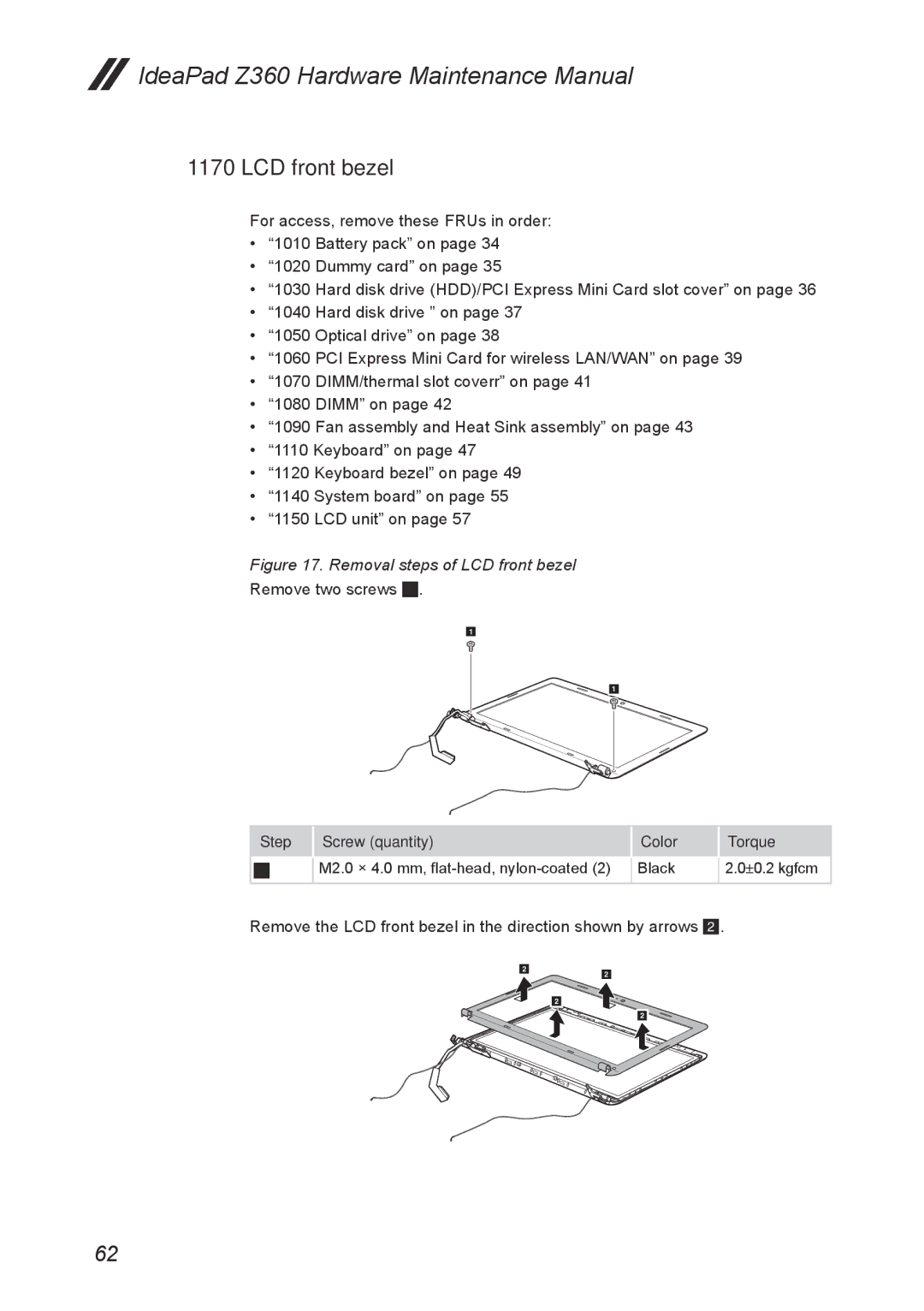
Figure 17. Removal steps of LCD front bezel
Remove two screws 1.
1
1
Step |
| Screw (quantity) |
| Color |
| Torque |
1 |
| M2.0 × 4.0 mm, |
| Black |
| 2.0±0.2 kgfcm |
|
|
| ||||
|
|
|
|
|
|
|
Remove the LCD front bezel in the direction shown by arrows 2.
2
2
2
2
62