APPLICATIONS: | IMPORTANT NOTICE |
Decora Electronic Controls will not control lighting that is used with low voltage or high frequency transformers, nor high pressure discharge lamps (HID lighting). This includes mercury vapor, sodium vapor, and metal halide lamps.
DEC components can control:
•Low pressure dischar e lamps (fluorescent) (ON/OFF only) - use dat. Nos. 6291 and 6293
•120 Volt quartz lamps can be dimmed or brightened - use Cat. Nos. 6381 and 6383
•Low volta e lighting can be controlled provided t!le lighting system operates with a 80 Hz transformer - (ON/OFF only) use Cat. Nos. 8291, 6293, 6227 and 6280 (DIMMING) use Cat. Nos.
If a power interruption should occur while the 6291 is ON the LOAD will remain ON when power is re- stored.
4
The Leviton power line carrier signal is designed to provide the greatest signal integrity and noise immunity possible. However, in some environments intense electrical noise can cause interference with the signal.
Leviton has developed hardware and techniques for overcoming this interference when properly applied. It is the responsibility of the specifier/installer to test for signal strength and the presence of noise using Leviton test equipment Cat. Nos. 6385 (Signal Test Transmitter) and 6386 (Signal Strength Indicator) and to properly apply signal coupling and noise- reduction equipment according to the guidelines provided in the DEC Technical Manual and the DEC Troubleshooting Guide.
Leviton specifically denies any warranty of perfor- mance, stated or implied, where electrical noise interference exists at the time of installation, or subsequent to Installation by the addition of noise- producing devices or equipment, or where these components have been installed for
5
INSTALLATION INSTRUCTIONS
1.WARNING: TO AVOID FIRE, SHOCK, OR DEATH; TURN OFF POWER AT CIRCUIT BREAKER OR FUSE. TEST THAT POWER IS
2.Remove and discard existing switch and wallplate, if applicable.
3.Remove 1/2” insulation from ends of branch drcuft wires to expose bare copper.
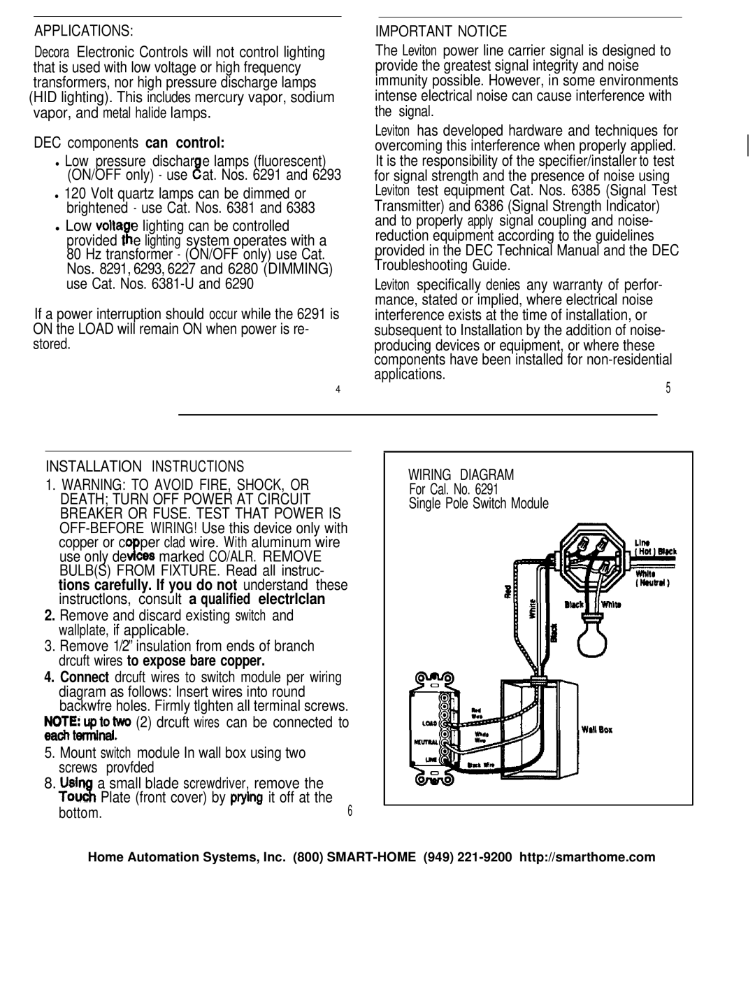
4.Connect drcuft wires to switch module per wiring diagram as follows: Insert wires into round backwfre holes. Firmly tlghten all terminal screws.
;FrtZx$two (2) drcuft wires can be connected to
5.Mount switch module In wall box using two screws provfded
8.Usi a small blade screwdriver, remove the Tout“aPlate (front cover) by pryin it off at the
bottom.6
WIRING DIAGRAM
For Cal. No. 6291
Single Pole Switch Module
Home Automation Systems, Inc. (800)