20/20 AD User GuideUsing the
The 20/20 AD has four analog inputs: CH1, CH2, CH3 and CH4. In
extended. If you have two stereo pairs, one of which is used more often than the other, the most often used pair should be assigned to CH1 and CH2, and the other pair to CH3 and CH4. This allows you to take advantage of the extended dynamic range of
When digitizing stereo pairs, the left channel of each pair should be sent to CH1 and CH3; the right to CH2 and CH4.
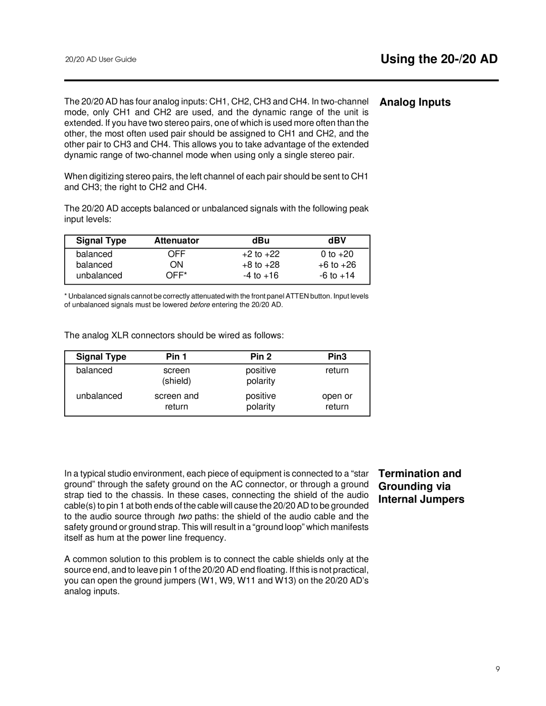
The 20/20 AD accepts balanced or unbalanced signals with the following peak input levels:
Signal Type | Attenuator | dBu | dBV | |
|
|
|
| |
balanced | OFF | +2 to +22 | 0 to +20 |
|
balanced | ON | +8 to +28 | +6 to +26 | |
unbalanced | OFF* |
|
| |
|
|
|
|
|
*Unbalanced signals cannot be correctly attenuated with the front panel ATTEN button. Input levels of unbalanced signals must be lowered before entering the 20/20 AD.
The analog XLR connectors should be wired as follows:
Signal Type | Pin 1 | Pin 2 | Pin3 |
|
|
|
|
balanced | screen | positive | return |
| (shield) | polarity |
|
unbalanced | screen and | positive | open or |
| return | polarity | return |
|
|
|
|
In a typical studio environment, each piece of equipment is connected to a “star ground” through the safety ground on the AC connector, or through a ground strap tied to the chassis. In these cases, connecting the shield of the audio cable(s) to pin 1 at both ends of the cable will cause the 20/20 AD to be grounded to the audio source through two paths: the shield of the audio cable and the safety ground or ground strap. This will result in a “ground loop” which manifests itself as hum at the power line frequency.
A common solution to this problem is to connect the cable shields only at the source end, and to leave pin 1 of the 20/20 AD end floating. If this is not practical, you can open the ground jumpers (W1, W9, W11 and W13) on the 20/20 AD’s analog inputs.
Termination and Grounding via Internal Jumpers
9