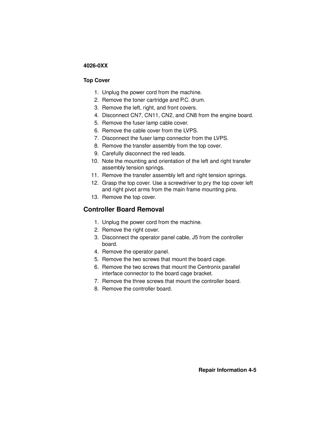
4026-0XX specifications
The Lexmark 4026-0XX is a robust monochrome laser printer designed specifically for small to medium-sized businesses that seek reliability, efficiency, and versatile printing capabilities. This model is part of Lexmark's renowned series of printers, known for their high-quality output and user-friendly features.One of the standout characteristics of the Lexmark 4026-0XX is its impressive print speed, capable of producing up to 40 pages per minute. This rapid output is ideal for busy office environments where time is of the essence. Additionally, it offers a first-page-out time as fast as 5.2 seconds, ensuring minimal wait time for crucial documents.
The printer is equipped with a printing resolution of up to 1200 x 1200 dots per inch (dpi), which guarantees sharp text and detailed graphics. This high-resolution output makes it suitable not just for standard documents, but also for more intricate prints that require precision.
Flexibility in paper handling is another prominent feature of the Lexmark 4026-0XX. It comes with a standard paper capacity of 250 sheets, expandable through optional trays, allowing users to manage various media types and sizes effortlessly. The printer supports a range of paper weights and formats, including letterhead and labels, making it a versatile tool for different printing tasks.
The Lexmark 4026-0XX also incorporates advanced security features, which are increasingly important in today’s business environments. With secure printing capabilities, users can ensure that sensitive documents are protected, needing proper authorization before being printed. Additionally, features such as IP filtering and encrypted PDF printing reinforce the security of confidential information.
Moreover, the printer supports various connectivity options including USB, Ethernet, and mobile printing technologies. This allows employees to print from various devices with ease, enhancing productivity and workflow. Furthermore, the printer is compatible with a variety of operating systems, ensuring broad access within a multi-device office setup.
In terms of operational efficiency, the Lexmark 4026-0XX employs innovative energy-saving technologies that reduce power consumption during inactive periods. This not only lowers energy costs but also supports corporate sustainability initiatives.
Overall, the Lexmark 4026-0XX is a powerful monochrome laser printer that combines speed, quality, and security, making it an excellent choice for organizations looking to enhance their printing capabilities while maintaining operational efficiency. Its blend of advanced features and reliability solidifies its position as a valuable asset in any business setting.
