READ THE SAFETY PRECAUTIONS IN THIS MANUAL
CHASSIS LD21B
SERVICE MANUAL
http//aic.lgservice.com
SERVICING PRECAUTIONS
CONTENTS
SAFETY PRECAUTIONS
SPECIFICATION
SAFETY PRECAUTIONS
IMPORTANT SAFETY NOTICE
SERVICING PRECAUTIONS
Electrostatically Sensitive ES Devices
Small-Signal Discrete Transistor Removal/Replacement
IC Remove/Replacement
Replacement
Removal
1. Application range
SPECIFICATION
4. Model General Specification
3. Test method
DVB-S2 8PSK / QPSK 2 ~ 45Msymbol/s
Symbolrate 4.0Msymbols/s to 7.2Msymbols/s
symbolrate
DVB-S QPSK 2 ~ 45Msymbol/s
5. Video resolutions 2D
5.1. Component Input Y, CB/PB, CR/PR
5.2. RGB Input PC
5.3. HDMI InputPC/DTV
PCDVI
1. Application Range
ADJUSTMENT INSTRUCTION
Boot file Download
2. Designation
3.2. EDID Download
3.1. ADC Process
3.3. EDID data
7. ADC Calibration
4. Total Assembly line process
4.1. Adjustment Preparation
3.4 Function Check
5. HI-POT Test
4.3. Outgoing condition Configuration
6.1. Signal Table
6. Model name & Serial number D/L
7.1 MAC Address
7. MAC Address & CI+ key download
6.3. Method & notice
GP4LOW
7.2 LAN Inspection
7.3. LAN PORT INSPECTIONPING TEST
ח ͷͲͳͤͤͤͪͥͣ͢͡ ͙;ͤ͛ͽͥͦ͑͟͝ͳͼ͑͝;ΒΔΙΚΟΖ͚ ח ͣ͢ͶͲ
SCREW ASSEMBLY WORKING GUIDE
Screw specification and application situation
ח ͷͲͳͤͨͩͩͣ͑͢͡͡ ͙;ͧ͛ͽ͑͢͡͝ͳͼ͑͝;ΒΔΙΚΟΖ͚
Side
BLOCK DIAGRAM
Rear
LG2111 A
EXPLODED VIEW
to delete CI or gate for
GP4LS7LR22011.12.01
Copyright 2012 LG Electronics. Inc. All rights reserved
for SYSTEM EEPROM
Normal
Normal Power
VDDC
DDR3
+3.3VNormal
FROM LIPS & POWER B/D
PowerDET
+1.5VDDR
IR/LED and control for normal models
USB SIDE
USB1DIODES
USB2DIODES
HDMI
SPECIAL FEATURES IMPORTANT FOR PROTECTION FROM X-RADIATION
RGB-PC / SPDIF
THE SYMBOL MARK OF THIS SCHEMETIC DIAGRAM INCORPORATES
FILRE AND ELECTRICAL SHOCK HAZARDS, WHEN SERVICING IF IS
RS-232C
COMMERCIAL/NonOS MODEL OPTION COMMERCIAL MODEL OPTION
For Comsumer model, use 4PIN Wafer
LVDS for large inch
IC1201
S7LR2DIVXMS10
GP4LS7LR22011/06/03 DDR25612
H5TQ1G63DFR-H9C
Serial Flash for SPI boot
SFLASHMAINMACRONIX
SFLASHMAINWINBOND IC1401-*1 W25Q80BVSSIG
Headphone *Option HEADPHONE
PHONE
HEAD
CI Region
Option name of this page CISLOT because of Hong Kong
10067972-0500LF
H/W option ETHERNET
GP4LS7LR22011/06/14 ETHERNET21
ETHERNET
TU2601
GP4RGLOBALTUNERBLOCK
TU2602TU2603 TDSS-G101D TDSN-G301D
TDSQ-G001D
GP4LS7LR22011/11/02 DVBS27
DVB-S2 LNB Part Allegro
OptionLNB
DCDCGND and AGND are connected
JK2801
SCART / COMPONENT&COMPSIT
FULL SCART / COMPONENT1
PSC008-01
AUDIO AMPSTA380BWE
Page
Contents of LCD TV Standard Repair Process
Error symptom
Contents of LCD TV Standard Repair Process Detail Technical Manual
Continue to the next page
Content
Main B/D↔ Power B/D, LVDS Cable,Speaker Cable,IR B/D Cable
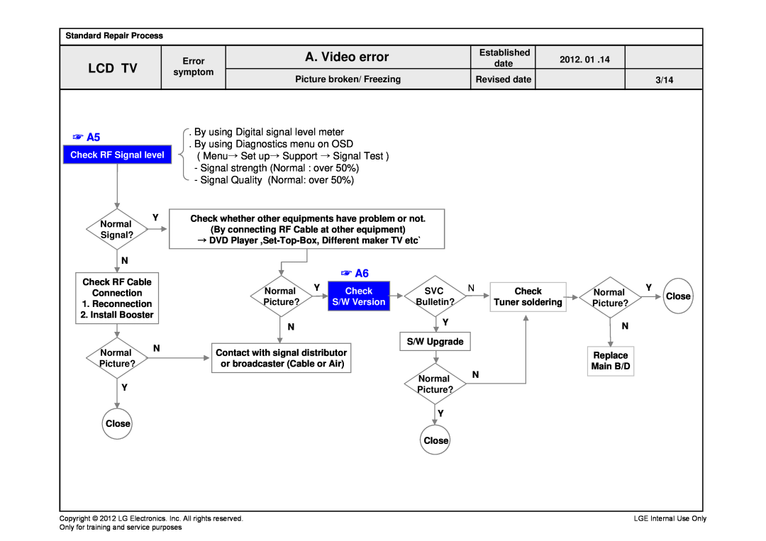
A. Video error
LCD TV
A2 Check Power Board 24v output
Board 3.5V,12V,20V
voltages of Power
Check various
or 24V…
By using Digital signal level meter By using Diagnostics menu on OSD
Menu→ Set up→ Support → Signal Test Signal strength Normal over 50%
Signal Quality Normal over 50%
→ Set-Top-Box, Different maker TV etc
※ Check
A8/ A9
Check color by input -External Input COMPONENT -RGB
Link Cable
Connect other external device and cable
External device screen error-Color error
Vertical/Horizontal bar, residual image, light spot
Check color condition by input -External Input -Component RGB
Check Power On ‘”High”
B. Power error
Check Power LED
Measure voltage of each output of Power B/D
POWEROFFABNORMAL1
Check Power Off Mode
If Power Off mode is not displayed Check Power B/D voltage
POWEROFFCPUABNORMAL
Check user menu Speaker off
C. Audio error
24V of Power
Check audio B+
In case of External Input signal error Check and fix external device
Check audio B+ Voltage
D. Function error
1. Remote controlR/C operating error
Check & Repair
Recognition error
Check input signal
Y Check technical Signal information input? - Fix information
Replace Main B/D
E. Noise
Identify nose type
F. Exterior defect