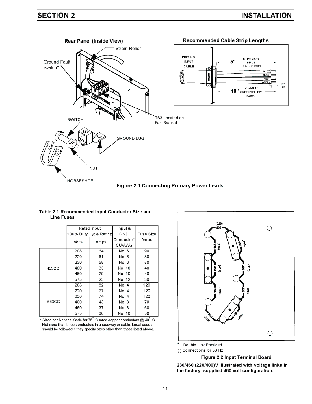
453cc, 553cc specifications
LG Electronics has made a significant mark in the world of home appliances and electronics, particularly with its innovative air conditioning systems. Among its impressive lineup are the 553cc and 453cc models, which exemplify cutting-edge technology and exceptional performance. These air conditioning units are designed to provide comfortable living environments while maximizing energy efficiency.The LG 553cc model stands out with its refined design and robust features. It comes equipped with advanced inverter technology, which allows for precise temperature control and energy savings. The inverter compressor operates at variable speeds, adjusting to the cooling requirements in real-time, resulting in quieter operation and reduced energy consumption. The 553cc unit is also designed with a high cooling capacity, making it suitable for larger rooms or open spaces, ensuring even temperature distribution throughout the area.
On the other hand, the LG 453cc model caters to smaller spaces while delivering efficient cooling performance. Its compact design does not compromise functionality, making it ideal for apartments or smaller homes. The 453cc model is also equipped with inverter technology, which allows households to enjoy significant energy savings without sacrificing comfort. This air conditioner operates silently, ensuring a peaceful indoor environment.
Both models feature a sleek, modern aesthetic that can blend seamlessly into various room decors. They come with user-friendly smart controls, allowing homeowners to monitor and adjust their air conditioning settings via smartphone apps, providing convenience and accessibility at your fingertips.
Moreover, LG has incorporated air purification technologies in both models. These systems utilize advanced filters to remove contaminants and allergens from the air, promoting a healthier indoor atmosphere. The unique design also emphasizes ease of maintenance, with accessible filters that can be cleaned or replaced easily.
In terms of durability, the materials used in the construction of the 553cc and 453cc models are built to withstand the test of time, with anti-corrosive coatings that increase longevity in varying climates.
Overall, the LG Electronics 553cc and 453cc air conditioning units represent the pinnacle of comfort, technology, and efficiency in modern cooling solutions, catering to diverse needs while ensuring an eco-friendly approach. Choosing either model means investing in a quality product that enhances indoor living spaces with minimal environmental impact.

