SECTION 2

INSTALLATION

D.Check all connections for proper tightness. En- sure all connections are correct and well insu- lated.

E.Figure 2-2 illustrates the input voltage terminal board and the input voltage link connections. The particular voltages from which this power source may be operated are stated on the rating plate. The voltage links were factory set for highest voltage stated on the rating plate. If the power source is to be operated on another stated input voltage, the links must be reset for that particular input voltage. Always verify the input voltage and check the link arrangement regardless of factory setting. The voltage links are set up by re-configuring the copper link bars to the silk screened voltage designations for the desired voltage.

2.4OUTPUT WELDING CONNECTIONS (SECONDARY)

Before making any connections to the power source output terminals, make sure that all primary input power to the machine is off.

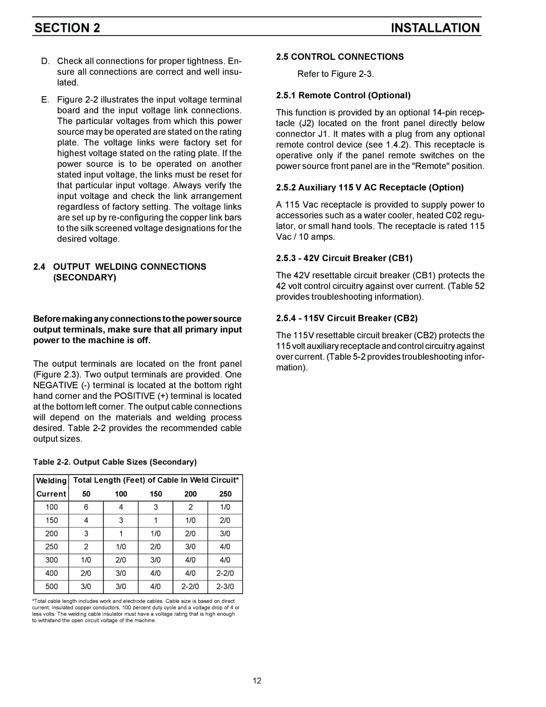
The output terminals are located on the front panel (Figure 2.3). Two output terminals are provided. One NEGATIVE (-) terminal is located at the bottom right hand corner and the POSITIVE (+) terminal is located at the bottom left corner. The output cable connections will depend on the materials and welding process desired. Table 2-2 provides the recommended cable output sizes.

Table 2-2. Output Cable Sizes (Secondary)

Welding

Total Length (Feet) of Cable In Weld Circuit*

Current

50

100

150

200

250


100

6

4

3

2

1/0


150

4

3

1

1/0

2/0


200

3

1

1/0

2/0

3/0


250

2

1/0

2/0

3/0

4/0


300

1/0

2/0

3/0

4/0

4/0


400

2/0

3/0

4/0

4/0

2-2/0


500

3/0

3/0

4/0

2-2/0

2-3/0


*Total cable length includes work and electrode cables. Cable size is based on direct current, insulated copper conductors, 100 percent duty cycle and a voltage drop of 4 or less volts. The welding cable insulator must have a voltage rating that is high enough to withstand the open circuit voltage of the machine.

2.5CONTROL CONNECTIONS Refer to Figure 2-3.

2.5.1 Remote Control (Optional)

This function is provided by an optional 14-pin recep- tacle (J2) located on the front panel directly below connector J1. It mates with a plug from any optional remote control device (see 1.4.2). This receptacle is operative only if the panel remote switches on the power source front panel are in the "Remote" position.

2.5.2 Auxiliary 115 V AC Receptacle (Option)

A 115 Vac receptacle is provided to supply power to accessories such as a water cooler, heated C02 regu- lator, or small hand tools. The receptacle is rated 115 Vac / 10 amps.

2.5.3 - 42V Circuit Breaker (CB1)

The 42V resettable circuit breaker (CB1) protects the 42 volt control circuitry against over current. (Table 52 provides troubleshooting information).

2.5.4 - 115V Circuit Breaker (CB2)

The 115V resettable circuit breaker (CB2) protects the 115 volt auxiliary receptacle and control circuitry against over current. (Table 5-2 provides troubleshooting infor- mation).

12

Page 12
Image 12
LG Electronics 553cc Output Welding Connections Secondary, Control Connections Refer to Figure Remote Control Optional

453cc, 553cc specifications

LG Electronics has made a significant mark in the world of home appliances and electronics, particularly with its innovative air conditioning systems. Among its impressive lineup are the 553cc and 453cc models, which exemplify cutting-edge technology and exceptional performance. These air conditioning units are designed to provide comfortable living environments while maximizing energy efficiency.

The LG 553cc model stands out with its refined design and robust features. It comes equipped with advanced inverter technology, which allows for precise temperature control and energy savings. The inverter compressor operates at variable speeds, adjusting to the cooling requirements in real-time, resulting in quieter operation and reduced energy consumption. The 553cc unit is also designed with a high cooling capacity, making it suitable for larger rooms or open spaces, ensuring even temperature distribution throughout the area.

On the other hand, the LG 453cc model caters to smaller spaces while delivering efficient cooling performance. Its compact design does not compromise functionality, making it ideal for apartments or smaller homes. The 453cc model is also equipped with inverter technology, which allows households to enjoy significant energy savings without sacrificing comfort. This air conditioner operates silently, ensuring a peaceful indoor environment.

Both models feature a sleek, modern aesthetic that can blend seamlessly into various room decors. They come with user-friendly smart controls, allowing homeowners to monitor and adjust their air conditioning settings via smartphone apps, providing convenience and accessibility at your fingertips.

Moreover, LG has incorporated air purification technologies in both models. These systems utilize advanced filters to remove contaminants and allergens from the air, promoting a healthier indoor atmosphere. The unique design also emphasizes ease of maintenance, with accessible filters that can be cleaned or replaced easily.

In terms of durability, the materials used in the construction of the 553cc and 453cc models are built to withstand the test of time, with anti-corrosive coatings that increase longevity in varying climates.

Overall, the LG Electronics 553cc and 453cc air conditioning units represent the pinnacle of comfort, technology, and efficiency in modern cooling solutions, catering to diverse needs while ensuring an eco-friendly approach. Choosing either model means investing in a quality product that enhances indoor living spaces with minimal environmental impact.