2.Installation
Speaker System Connection
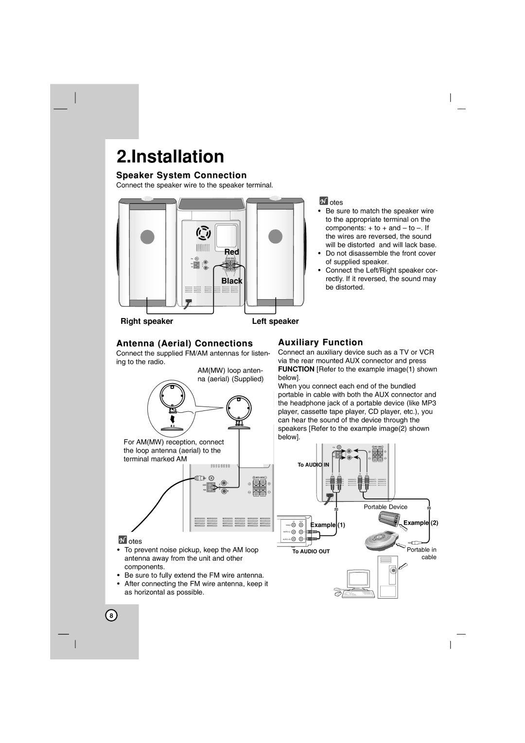
Connect the speaker wire to the speaker terminal.
| Red | |
FM | R | L |
| L |
|
GND | A |
|
| U |
|
AM | X |
|
| R |
|
| Black | |
Right speaker | Left speaker |
![]() otes
otes
•Be sure to match the speaker wire to the appropriate terminal on the components: + to + and – to
•Do not disassemble the front cover of supplied speaker.
•Connect the Left/Right speaker cor- rectly. If it reversed, the sound may be distorted.
Antenna (Aerial) Connections
Connect the supplied FM/AM antennas for listen- ing to the radio.
AM(MW) loop anten- na (aerial) (Supplied)
For AM(MW) reception, connect the loop antenna (aerial) to the ![]() terminal marked AM
terminal marked AM ![]()
![]()
![]()
![]()
![]()
![]()
![]()
![]()
Auxiliary Function
Connect an auxiliary device such as a TV or VCR via the rear mounted AUX connector and press FUNCTION [Refer to the example image(1) shown below].
When you connect each end of the bundled portable in cable with both the AUX connector and the headphone jack of a portable device (like MP3 player, cassette tape player, CD player, etc.), you can hear the sound of the device through the speakers [Refer to the example image(2) shown below].
FM | R | L |
| L |
GND | A |
| U |
AM | X |
| R |
To AUDIO IN
FM
GND
AM
R | L |
L |
|
A |
|
U |
|
X |
|
R |
|
![]() otes
otes
•To prevent noise pickup, keep the AM loop antenna away from the unit and other components.
•Be sure to fully extend the FM wire antenna.
•After connecting the FM wire antenna, keep it as horizontal as possible.
|
| Portable Device |
VIDEO | IN OUT | Example (2) |
| Example (1) |
|
AUDIO (L) |
|
|
AUDIO (R) |
|
|
| To AUDIO OUT | Portable in |
|
| cable |
8