Introduction
Connection Options
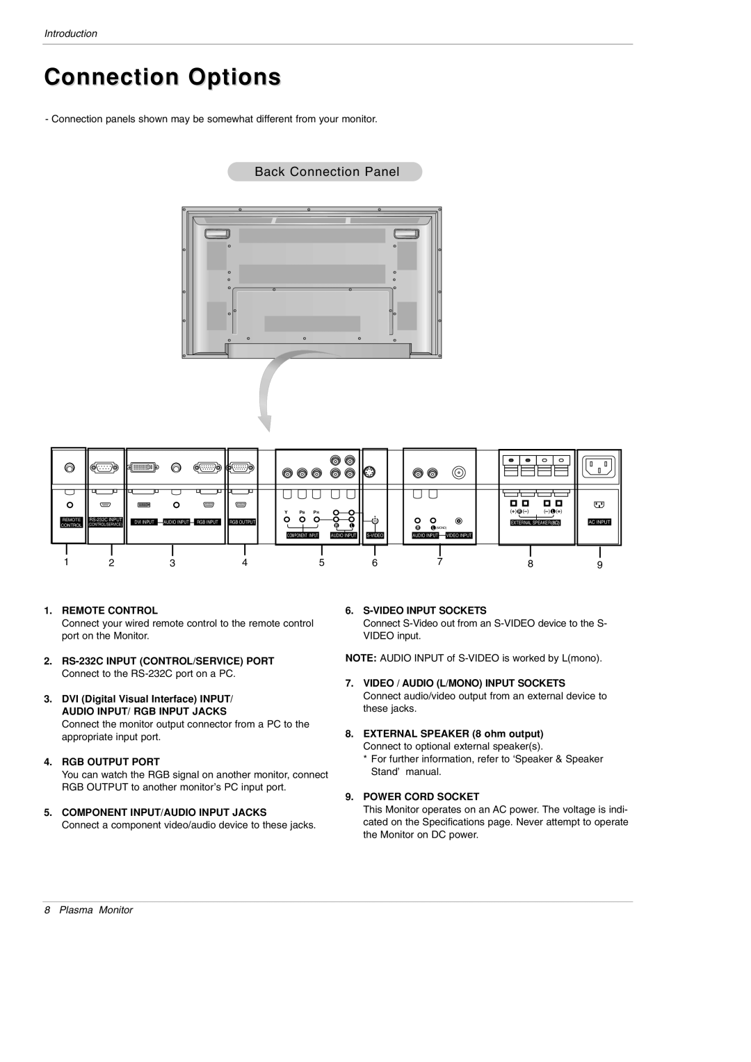
- Connection panels shown may be somewhat different from your monitor.
Back Connection Panel
REMOTE
CONTROL
(CONTROL/SERVICE)
|
|
|
|
|
|
|
|
|
|
|
|
| DVI INPUT |
| AUDIO INPUT |
| RGB INPUT |
|
| RGB OUTPUT |
| ||
|
|
|
| ||||||||
|
|
|
|
|
|
|
|
|
|
|
|
|
|
|
|
|
|
|
|
|
|
|
|
Y PB PR
R L
COMPONENT INPUT |
| AUDIO INPUT |
RL (MONO)
AUDIO INPUT |
| VIDEO INPUT |
| ||
|
|
|
( ) R ( ) | ( ) L ( ) |
EXTERNAL SPEAKER![]()
![]()
AC INPUT
1 | 2 | 3 | 4 | 5 | 6 | 7 | 8 | 9 |
1.REMOTE CONTROL
Connect your wired remote control to the remote control port on the Monitor.
2.
3.DVI (Digital Visual Interface) INPUT/ AUDIO INPUT/ RGB INPUT JACKS
Connect the monitor output connector from a PC to the appropriate input port.
4.RGB OUTPUT PORT
You can watch the RGB signal on another monitor, connect RGB OUTPUT to another monitor’s PC input port.
5.COMPONENT INPUT/AUDIO INPUT JACKS
Connect a component video/audio device to these jacks.
6.S-VIDEO INPUT SOCKETS
Connect
NOTE: AUDIO INPUT of
7.VIDEO / AUDIO (L/MONO) INPUT SOCKETS Connect audio/video output from an external device to these jacks.
8.EXTERNAL SPEAKER (8 ohm output) Connect to optional external speaker(s).
*For further information, refer to ‘Speaker & Speaker Stand’ manual.
9.POWER CORD SOCKET
This Monitor operates on an AC power. The voltage is indi- cated on the Specifications page. Never attempt to operate the Monitor on DC power.
8 Plasma Monitor