U250/KU250
Table Of Contents
Page
Purpose
Regulatory Information
Interference and Attenuation
Pictures
Electrostatic Sensitive Devices
Specification
System Overview
Environment Accessory
Transmitter GSM Mode
Usable environment
Radio Performance
Case of DCS a 1710, B Case of PCS a 1850, B
Power Tolerance
Transmitter Wcdma Mode
3Receiver GSM Mode
Receiver Wcdma Mode
Current Consumption
U250/KU250 Current Consumption
Stand by Voice Call
Level Change
Battery BAR
Indication Standby
Sound Pressure Level
Test Item Specification
Charging
Block diagram of RF part
General Description
Technical Brief
Antenna Switch Module Control logic
GSM Mode
GSM Receiver
Technical Brief
RTR6275 RX feature
GSM Transmitter
GSM Transmitter matching
Receiver
Umts Mode
Transmitter
RTR6275 IC functional block diagram
Off-chip RF Components
LO generation and distribution circuits
Wcdma PAM U103 WS2512-TR1G
Front-End Module U500 D5011
Vctcxo X100 DSA321SCE-19.2M
Front End Module control logic
Pmic Functional Block Diagram U300 PM6650-2M
Usbotg
MSM6245 Interface
PM6650 Block Diagram
GSM PAM Schematic
GSM PAM U101 SKY77318
Umts DuplexerFL104ACMD-7602
Wcdma Rx SAW Filter Specification
Umts Rx RF filter FL103 EFCH2140TDE1
Bluetooth M100 LBRQ-2B43A
MSM6245 Bluetooth Baseband
Digital BasebandDBB/MSM6245
General Description
PM6650
RTR6275
Nand Flash
Block DiagramMSM6245
512Mbit 76inch
SubsystemMSM6245
Wcdma R99 features
ARM Microprocessor Subsystem
Gprs features
GSM features
Edge features
Supported interface features
MSM6245 device audio processing features
MSM6245 microprocessor subsystem
Supported multimedia features
Video telephony services QvideophoneTM
QcameraTM
QtvTM
Summary of MSM6245 device features
Description of RF configurations
Stereo Wideband Codec
Mode Select and Jtag Interfaces
Vocoder Subsystem
Uart
General-Purpose Input/Output Interface
USB
General
Power Block
2. PM6650
12 PM6650 Functional Block Diagram
13 U250/KU250 Battery Bar DisplayStand By Condition
Charging control
Trickle Charging
Parameter Min Typ Max Unit Trickle Current 100
Constant Current Charging
Constant Voltage Charging
External memory interface
Table#1. External memory interface
512Mb
64MB
DATA310
DQM30
RF Interface
11 H/W Sub System
RTR6275WCDMATx, GSMTx/Rx
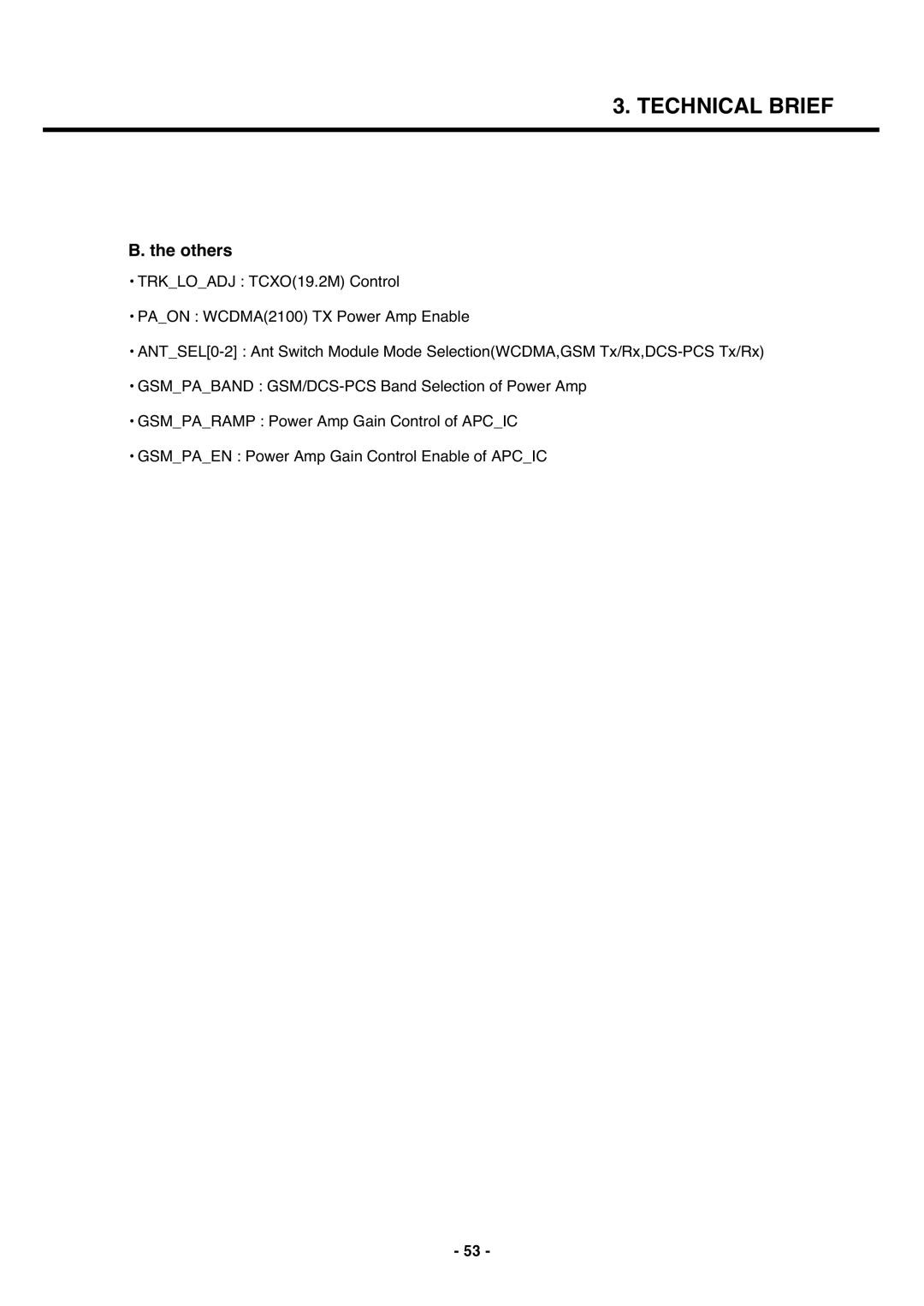
Others
MSM Sub System
Usim Interface
GPIOMap Name
Table. Uart Interface
Table. USB Signal Interface
USB
HKADCHouse Keeping ADC
Table. Hkadc channel table
Key Pad
Table. Key Matrix Mapping Table
21 Camera Socket Type Connector
Camera Interface
CAMDATAOUT3
Dvdd
22 Schematic of KEY back light circuit KEY side
Keypad Light
LCD Module NM176CN1 Tovis
Display & LCD FPC Interface
Audio Signal Processing & Interface
24 Audio Interface Detailed DiagramMSM6245
MSM6245 Codec pins
25 Audio part schematics
MIC
Audio part schematics
Audio AMP
Audio Mode
Main Features
LG-U250/KU250 Main features
Logic Audio Bluetoot
SW100 U101 U500 FL101 U100 FL104 U103 X100
Logic / Audio
U301
S300
Trouble Shooting
RF Component
Umts
Signal Pathumts RF
Signal Pathgsm RF
Checking VC-TCXO Block
Schematic of the VC-TCXO Block
Test Point of the VC-TCXO Block
Check C312 of Pmic U300 Check R213 of MSM U201
Checking Front-End Module Block
Schematic of the Front-End Module Block
Test Point of the Front-End Module Block
Logic Table of the FEM
Checking Umts Block
For testing, Max power of UMT 2100 is needed
Checking Tx level
Trouble Shooting
Checking Umts PAM Control Block PAM control signal
Checking RF Rx Level
TP2 TP4
Trouble Shooting
Checking GSM Block
Schematic of RF Tx level
Checking RF Tx level
Trouble Shooting
Checking PAM Block
TP1 TP4 TP2TP3
Checking RF Rx Block
TP1. DCS RX Input
Trouble Shooting
Checking Bluetooth Block
Bluetooth
Signals exits?
Change the M100 Signals exits?
Start
Change the Main board
Power on Troubleshooting
Vregmsmc Vregmsme Vregmsmp
Charger Troubleshooting
Charger
Connection OK?
Change the board Charger Troubleshooting Flow
Change TA Or USB Cable
Q301
Q302
Charging part Main PCB Front
USB Troubleshooting
Go to power on trouble shooting
Cable is inserted? Insert cable
Q400 pin 4 is 5V? Check Q300 pin
SIM Detect Troubleshooting
Start Re-insert the SIM card
Yes
End
Usim
Camera Troubleshooting
Start
Yes Camera is OK?
Yes Check the Cammclk
Yes
Change the Main board 103
U303C348 C349
C350 C447 U501
104
Keypad Backlight Troubleshooting
Figure.Keypad backlight LED part 105
Main LCD Troubleshooting
106
Receiver Path
107
108
Headset path
109
110
Speaker phone path
111
112
Main microphone
113
114
Headset microphone
115
116
Work well? Yes End
Vibrator
117
118
U250/KU250 Download
Downloading Procedure
Introduction
Connecting to PC
120
EraseEFS
Keep All Contents
121
Choosing image files
122
123
124
Downloading
125
126
127
Tools
128
Troubleshooting Download Errors
129
130
NV Restore Error
131
132
Port number
133
U250/KU250 RF Functional Block Diagram 134
GSM & Umts RF Block
RF Block Component 135
1 RTR6275 & MSM6245 Interface Diagram
Interface Diagram
RTR6275 & MSM6245 Interface Diagram 136
Memory Interface Diagram 137
Memory Interface
3 USB,UART,SIM,JTAG Interface
USB, UART, SIM, Jtag Interface 138
Main RF signal Control signal
139
Placement Top Side
140
Bottom Side
141
142
Circuit Diagram
143
144
Nand & LCD
145
EBI2WEN Nandready Nandale Nandcle Resoutn EBI2OEN
LCD Connector
146
147
148
Configuration of directory
Configuration of HOT Kimchi
149
150
151
MSVCP60D.DLL MSVCRTD.DLL
Procedure
How to use HOT Kimchi
152
153
Test Program Setting
154
Wcdma Test Mode
155
GSM Test Mode
156
Exploded View & Replacement Part List
157
158
Replacement Parts Mechanic component
159
160
Replacement Parts Main component
161
162
163
164
165
166
167
DUPLEXER,IMT
168
169
170
171
RES,ARRAY,R
172
Vctcxo
173
Accessory
174
