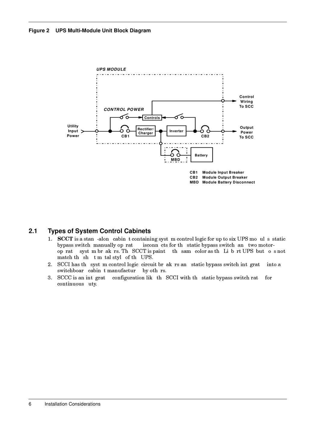
Figure 2 UPS Multi-Module Unit Block Diagram
UP S MODU LE
CON TR OL PO W ER
| Utility | | Rectifier/ | |
| Input | | In verter |
| | Charger |
| Pow er | CB 1 | CB2 |
| |
| | | | Battery |
| | | | M BD |
Control
W iring
To S CC
O utput
Pow er
To S CC
CB1 | M odule Input B reaker |
CB2 | M odule O utput Breaker |
MBD | Module Battery D isconnect |
2.1Types of System Control Cabinets
6Installation12I3.SCCbypassswitch,operatedswirdmacontinuCCTchbhasonsideraistheisausdutysystathenshintegratedconfigurationtandcabinetsystemionsmanully.-metalbreakerslonemanucotrolstylecabinetopera.TheSCCTacturedoflogic,thecontainigdiscoUPScircuitbylikeothersn.painednecbeakerssystem.SCCIforthecontrolthewithandsamestaticstaticthestaticcolorgicbypassfortheLiebertupbypasswitch,andtoswitchsixswitchUPSntegratedUPS,twmobutdules,motrforintoesstatic-not