10.0WIRING INSPECTION
Table4321.Verifyphase1
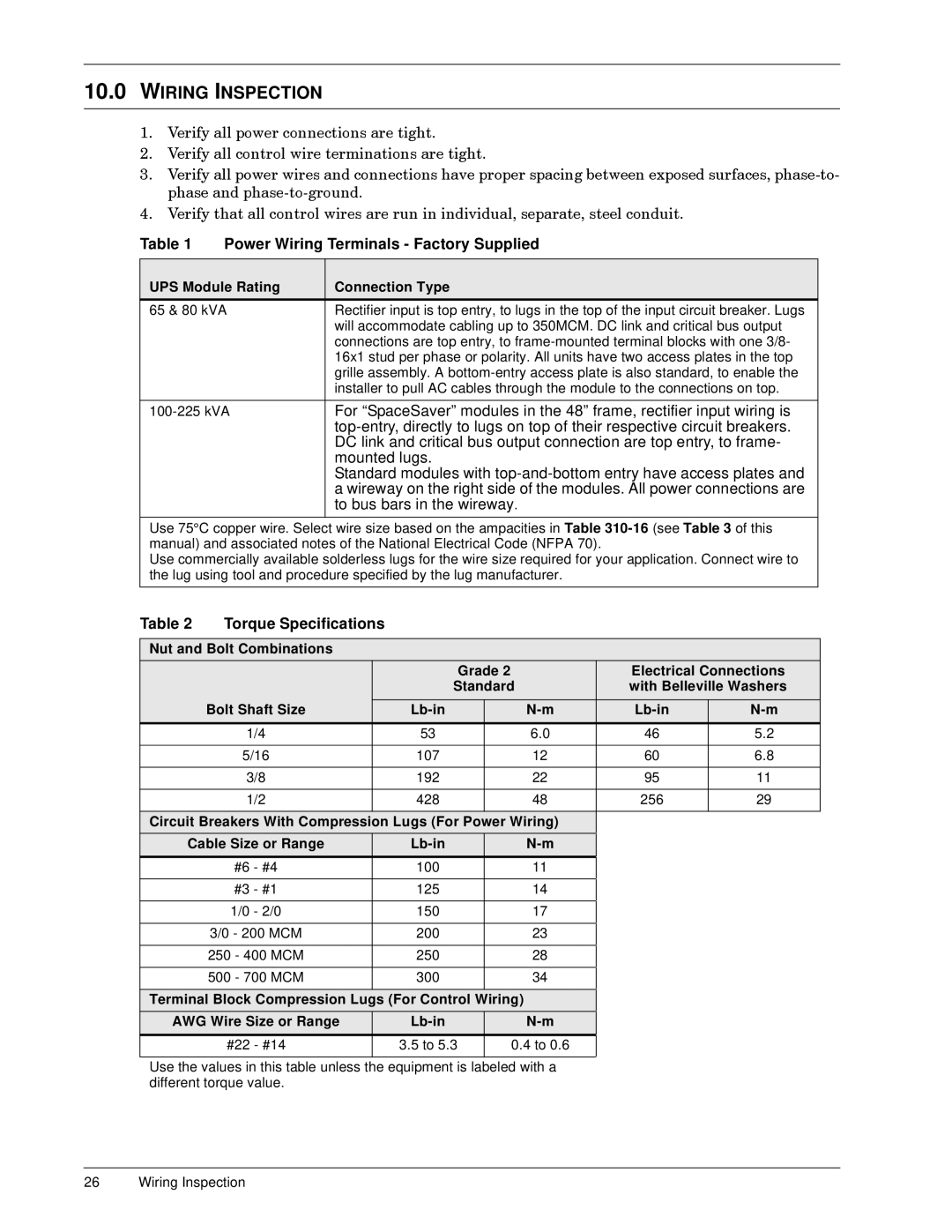
UPS Module Rating |
| Connection Type |
65 & 80 kVA |
| Rectifier input is top entry, to lugs in the top of the input circuit breaker. Lugs |
|
| will accommodate cabling up to 350MCM. DC link and critical bus output |
|
| are top entry, to |
|
| 16x1 stud per phase or polarity. All units have two access plates in the top |
|
| grille assembly. A |
|
| installer to pull AC cables through the module to the connections on top. |
|
|
|
| For “SpaceSaver” modules in the 48” frame, rectifier input wiring is | |
|
| |
|
| DC link and critical bus output connection are top entry, to frame- |
|
| mounted lugs. |
|
| Standard modules with |
|
| wireway the right side of the modules. All power connections are |
|
| to bus bars in the wireway. |
|
|
|
Use 75°C copper wire. Select | size based on the ampacities Table | |
manual) and associated notes of the National Electrical Code (NFPA 70). | ||
Use commercially available solderless lugs for the wire size required for your application. Connect wire to the lug using tool and procedure specified by the lug manufacturer.
Table 2 | Torque Specifications |
|
|
|
|
|
| |
|
|
|
|
|
|
|
| |
Nut and Bolt Combinations |
|
|
|
|
|
| ||
|
|
|
| Grade 2 |
| Electrical Connections | ||
|
|
| Standard |
| with Belleville Washers | |||
|
|
|
|
|
|
|
|
|
| Bolt Shaft Size |
|
|
| ||||
|
|
|
|
|
|
|
|
|
| 1/4 |
| 53 |
|
| 6.0 | 46 | 5.2 |
|
|
|
|
|
|
|
|
|
| 5/16 |
| 107 |
|
| 12 | 60 | 6.8 |
|
|
|
|
|
|
|
|
|
| 3/8 |
| 192 |
|
| 22 | 95 | 11 |
|
|
|
|
|
|
|
|
|
| 1/2 |
| 428 |
|
| 48 | 256 | 29 |
|
|
|
|
| ||||
Circuit Breakers With Compression Lugs (For Power Wiring) |
|
| ||||||
Cable Size or Range |
|
|
|
|
| |||
| #6 - #4 |
| 100 |
|
| 11 |
|
|
|
|
|
|
|
|
|
|
|
| #3 - #1 |
| 125 |
|
| 14 |
|
|
|
|
|
|
|
|
|
|
|
| 1/0 - 2/0 |
| 150 |
|
| 17 |
|
|
|
|
|
|
|
|
|
|
|
| 3/0 - 200 MCM |
| 200 |
|
| 23 |
|
|
|
|
|
|
|
|
|
|
|
| 250 - 400 MCM |
| 250 |
|
| 28 |
|
|
|
|
|
|
|
|
|
|
|
| 500 - 700 MCM |
| 300 |
|
| 34 |
|
|
|
|
|
|
|
| |||
Terminal Block Compression Lugs (For Control Wiring) |
|
|
| |||||
AWG Wire Size or Range |
|
|
|
|
| |||
|
|
|
|
|
|
|
| |
| #22 - #14 |
| 3.5 to 5.3 |
| 0.4 to 0.6 |
|
| |
|
|
|
|
| ||||
Use the values in this table unless the equipment is labeled with a |
|
| ||||||
different torque value. |
|
|
|
|
|
| ||
26 Wiring Inspection