Hardware and Components
Enclosure
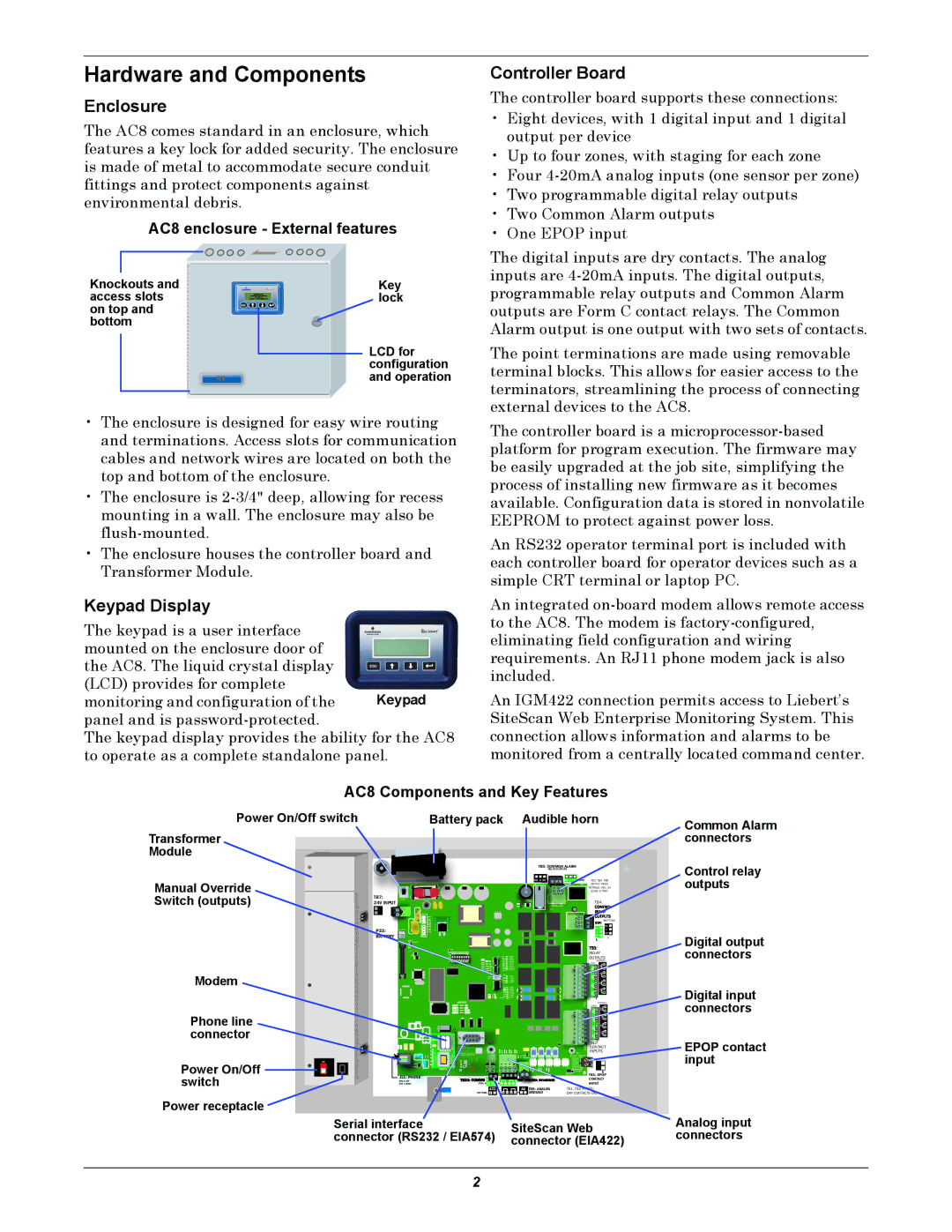
The AC8 comes standard in an enclosure, which features a key lock for added security. The enclosure is made of metal to accommodate secure conduit fittings and protect components against environmental debris.
AC8 enclosure - External features
Knockouts and | Key |
access slots | lock |
on top and |
|
bottom |
|
LCD for configuration and operation
•The enclosure is designed for easy wire routing and terminations. Access slots for communication cables and network wires are located on both the top and bottom of the enclosure.
•The enclosure is
•The enclosure houses the controller board and Transformer Module.
Keypad Display
The keypad is a user interface mounted on the enclosure door of the AC8. The liquid crystal display (LCD) provides for complete
monitoring and configuration of the Keypad panel and is
The keypad display provides the ability for the AC8 to operate as a complete standalone panel.
Controller Board
The controller board supports these connections:
•Eight devices, with 1 digital input and 1 digital output per device
•Up to four zones, with staging for each zone
•Four
•Two programmable digital relay outputs
•Two Common Alarm outputs
•One EPOP input
The digital inputs are dry contacts. The analog inputs are
The point terminations are made using removable terminal blocks. This allows for easier access to the terminators, streamlining the process of connecting external devices to the AC8.
The controller board is a
An RS232 operator terminal port is included with each controller board for operator devices such as a simple CRT terminal or laptop PC.
An integrated
An IGM422 connection permits access to Liebert’s SiteScan Web Enterprise Monitoring System. This connection allows information and alarms to be monitored from a centrally located command center.
AC8 Components and Key Features
Power On/Off switch | Battery pack Audible horn |
Transformer
Module
|
|
|
|
| TB5: COMMON ALARM |
|
| |
|
|
|
|
|
| RELAY OUTPUTS |
|
|
Manual Override |
|
|
|
| NO C NC | NO C | TB3, TB4, TB5 | |
|
|
|
| + |
| OUTPUT RELAY | ||
|
|
|
|
|
|
| RATINGS: 24V, 3A | |
Switch (outputs) |
|
|
|
|
|
| CLASS 2 ONLY. | |
TB7: | START |
|
| Q11 |
|
|
| |
|
|
| ENABLE | TOP | TB4: |
| ||
| 24V INPUT |
|
|
| AUDIBLE |
| ||
|
|
| BARCODE | LIEBERT |
|
| NO | (BOTTOM) |
| P23: |
|
|
|
|
|
| NC |
|
|
|
|
|
| C | NO | |
|
| BATTERY |
|
|
|
| NC | C |
|
|
|
|
|
|
|
| 2 |
Common Alarm connectors
Control relay outputs
Modem
Phone line connector
ON |
Power On/Off |
switch |
LCD |
|
CONTRAST |
|
VBATT | RELAY |
| |
| OUTPUTS |
| (BOTTOM) |
| (TOP) |
CAN TX | 4 |
CAN RX | |
| 7 |
| 3 |
6 |
2 |
5 |
1 |
| MODEM |
|
|
|
| REV | (BOTTOM) |
|
|
|
|
|
| (TOP) | |
|
|
|
|
|
|
| 8 |
|
|
|
|
|
|
| 4 |
|
|
|
|
|
|
| 7 |
|
|
|
|
|
|
| 3 |
|
|
|
|
|
|
| 6 |
|
|
|
|
|
|
| 2 |
|
|
|
|
|
|
| 5 |
|
|
|
|
|
|
| 1 |
|
|
|
|
|
| ASS | TB2: |
|
|
|
|
|
| CONTACT | |
|
|
|
|
| TB1 | INPUTS | |
|
|
| BOTTOM | EPOP INPUT |
| ||
|
|
|
| TOP |
|
|
|
|
|
|
|
|
| EPOP |
|
| MODEM |
|
|
|
| P19 |
|
|
|
|
|
|
| EPOP |
|
J11: PHONE |
|
|
|
|
| DIS EN | TB1: EPOP |
| 485 |
|
|
|
| CONTACT | |
PIN |
|
|
|
|
| ||
PIN | (TOP) | + — | + — + — |
|
|
| INPUT |
|
| 422 | AG | TB9: ANALOG | TB1, TB2 |
| |
| (BOTTOM) + — | + — + — |
| GROUND | DRY CONTACTS | ||
Digital output connectors
Digital input connectors
EPOP contact input
Power receptacle
Serial interface | SiteScan Web |
connector (RS232 / EIA574) | connector (EIA422) |
Analog input connectors
2