impeding condensate flow when duct pressures are below atmosphere.
6.The condensate line can go to either of two large holes in the fill cup cover on top of humidifier.
7.It is not necessary to return the condensate to the humidifier.
8.Long condensate runs (more than twenty feet) should be sloped well and be constructed out of ½" nominal copper pipe to ensure flow.
ELECTRICAL
PRIMARY VOLTAGE SUPPLY WIRING TO HUMIDIFIER
1.Check and ensure that available voltage and phase corresponds with operating voltage and phase of humidifier as indicated on the humidifier nameplate label (see Figure #1).
2.Ensure that an adequate power supply is available to carry full humidifier amperage drawn as specified by rated amps on the humidifier nameplate label refer to local codes.
3.A dedicated external disconnect must be installed. Do not exceed the maximum circuit protection amps as indicated on the nameplate label.
4.Connect ground wire to cabinet ground clamp. Do not use neutral wire of four wire supply as ground.
5.Single phase humidifiers may be run on three phase power, but load may unbalance power grid.
6.External wiring sizes must be in accordance with NEC and/or CEC and existing local electrical codes and
PRIMARY VOLTAGE SUPPLY WIRING FROM HUMIDIFIER(S) TO BLOWER PACKS
1.All blower packs are wired (by factory if
2.As a safety feature, blower packs come equipped with a manual reset safety thermostat and relay built into the blower pack cabinet. The manual reset thermostat turns off the humidifier if the blower pack gets overheated. The control thermostat, mounted
on the steam distributor, starts the fan when steam is generated.
3.All blower packs have high efficiency blowers to minimize the frontal and overhead clearance required to absorb the steam.
4.All
5.Remote mounted blower packs require field wiring between two primary voltage terminal blocks and two low voltage control (class 1 circuit wiring required) terminal strips; one of each located in humidifier and remote blower pack cabinet. To properly access the primary block on the humidifier, it may be necessary to remove the side. To connect the primary and control (class 1 circuit wiring required) wiring, the wiring is fed through the knockouts provided in the bottom of the blower pack. The terminal block and strip are accessed by removing the blower pack cover.
6.Field wiring of remote blower packs must conform to national and local electrical codes. Refer to wiring diagram supplied inside the humidifier.
7.Use approved wire for power connection from two pole terminal block of remote blower pack to additional two pole terminal block inside electrical section of humidifier.
8.Use approved wire to connect from ground clamp of remote mounted blower pack to ground clamp provided in the electrical section of humidifier.
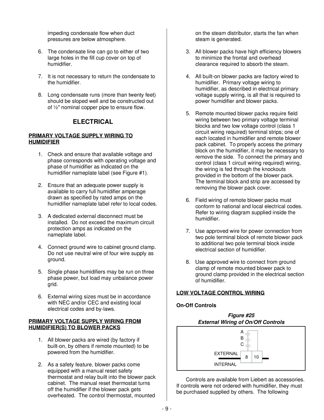
LOW VOLTAGE CONTROL WIRING
On-Off Controls
Figure #25
External Wiring of On/Off Controls
A
B ![]()
C ![]()
EXTERNAL
8 10
INTERNAL
Controls are available from Liebert as accessories. If controls were not ordered with humidifier, they must be purchased supplied by others. The following
- 9 -