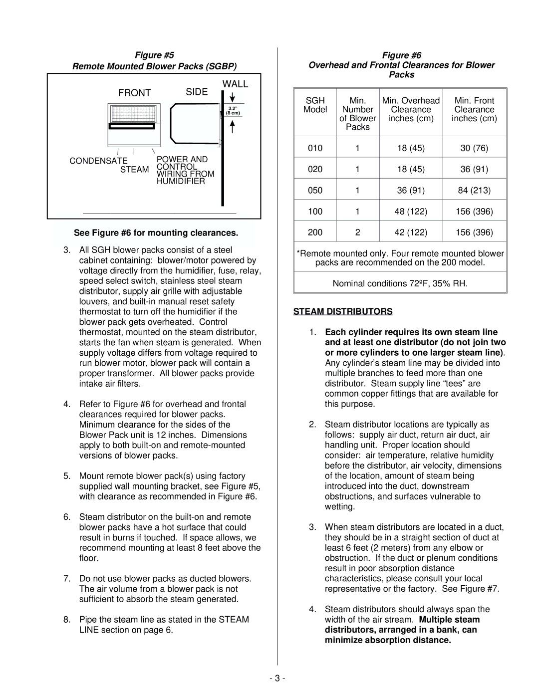
Figure #5
Remote Mounted Blower Packs (SGBP)
|
|
| WALL |
| FRONT |
| SIDE |
|
|
| 3.2” A |
|
|
| (8 cm) |
CONDENSATE | POWER AND | ||
| STEAM | CONTROL | |
|
| WIRING FROM | |
|
| HUMIDIFIER | |
|
| ||
|
| ||
See Figure #6 for mounting clearances. | |||
A | 3.2" (8.0cm) | 3.2" (8.0cm) | |
3.All SGH blower packs consist of a steel cabinet containing: blower/motor powered by voltage directly from the humidifier, fuse, relay, speed select switch, stainless steel steam distributor, supply air grille with adjustable louvers, and
4.Refer to Figure #6 for overhead and frontal clearances required for blower packs. Minimum clearance for the sides of the Blower Pack unit is 12 inches. Dimensions apply to both
5.Mount remote blower pack(s) using factory supplied wall mounting bracket, see Figure #5, with clearance as recommended in Figure #6.
6.Steam distributor on the
7.Do not use blower packs as ducted blowers. The air volume from a blower pack is not sufficient to absorb the steam generated.
8.Pipe the steam line as stated in the STEAM LINE section on page 6.
Figure #6
Overhead and Frontal Clearances for Blower
Packs
SGH | Min. | Min. Overhead | Min. Front | |
Model | Number | Clearance | Clearance | |
| of Blower | inches (cm) | inches (cm) | |
| Packs |
|
|
|
|
|
|
|
|
010 | 1 | 18 (45) | 30 | (76) |
|
|
|
|
|
020 | 1 | 18 (45) | 36 | (91) |
|
|
|
| |
050 | 1 | 36 (91) | 84 (213) | |
|
|
|
|
|
100 | 1 | 48 (122) | 156 | (396) |
|
|
|
|
|
200 | 2 | 42 (122) | 156 | (396) |
|
|
|
|
|
*Remote mounted only. Four remote mounted blower
packs are recommended on the 200 model.
Nominal conditions 72ºF, 35% RH.
STEAM DISTRIBUTORS
1.Each cylinder requires its own steam line and at least one distributor (do not join two or more cylinders to one larger steam line). Any cylinder’s steam line may be divided into multiple branches to feed more than one distributor. Steam supply line “tees” are common copper fittings that are available for this purpose.
2.Steam distributor locations are typically as follows: supply air duct, return air duct, air handling unit. Proper location should consider: air temperature, relative humidity before the distributor, air velocity, dimensions of the location, amount of steam being introduced into the duct, downstream obstructions, and surfaces vulnerable to wetting.
3.When steam distributors are located in a duct, they should be in a straight section of duct at least 6 feet (2 meters) from any elbow or obstruction. If the duct or plenum conditions result in poor absorption distance characteristics, please consult your local representative or the factory. See Figure #7.
4.Steam distributors should always span the width of the air stream. Multiple steam distributors, arranged in a bank, can minimize absorption distance.
- 3 -
