Controls and displays

3 Controls and displays

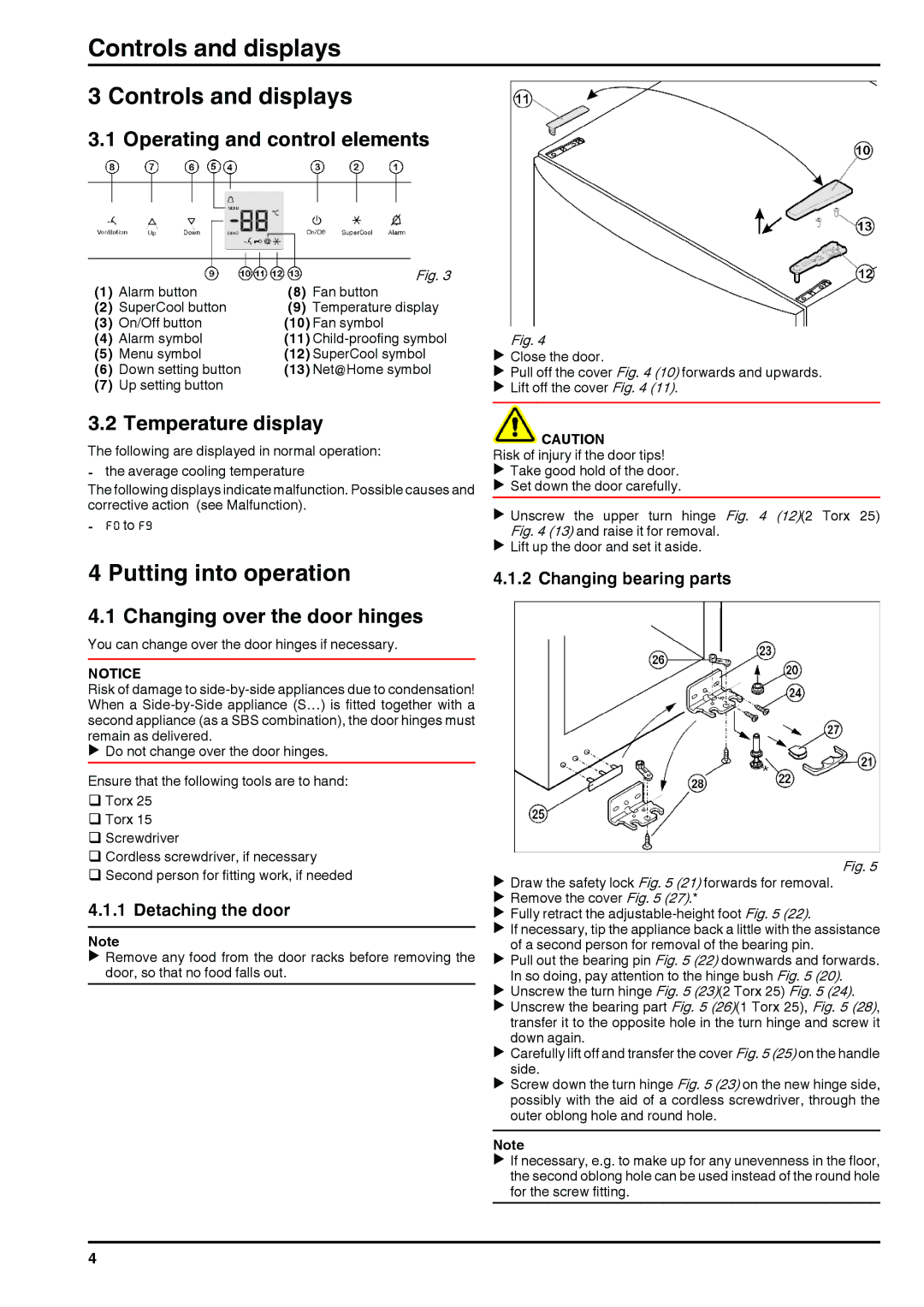
3.1 Operating and control elements

(1)

Alarm button

(8)

Fig. 3

Fan button

(2)

SuperCool button

(9)

Temperature display

(3)

On/Off button

(10) Fan symbol

(4)

Alarm symbol

(11) Child-proofing symbol

(5)

Menu symbol

(12) SuperCool symbol

(6)

Down setting button

(13) Net@Home symbol

(7)

Up setting button


3.2 Temperature display

The following are displayed in normal operation:

-the average cooling temperature

The following displays indicate malfunction. Possible causes and corrective action (see Malfunction).

-F0 to F9

4 Putting into operation

4.1 Changing over the door hinges

You can change over the door hinges if necessary.

NOTICE

Risk of damage to side-by-side appliances due to condensation! When a Side-by-Side appliance (S…) is fitted together with a second appliance (as a SBS combination), the door hinges must remain as delivered.

u Do not change over the door hinges.

Ensure that the following tools are to hand: q Torx 25

q Torx 15

qScrewdriver

qCordless screwdriver, if necessary

qSecond person for fitting work, if needed

4.1.1 Detaching the door

Note

u Remove any food from the door racks before removing the door, so that no food falls out.

Fig. 4

uClose the door.

uPull off the cover Fig. 4 (10) forwards and upwards.

uLift off the cover Fig. 4 (11).

CAUTION

Risk of injury if the door tips! u Take good hold of the door. u Set down the door carefully.

u Unscrew the upper turn hinge Fig. 4 (12)(2 Torx 25) Fig. 4 (13) and raise it for removal.

u Lift up the door and set it aside.

4.1.2 Changing bearing parts

Fig. 5

uDraw the safety lock Fig. 5 (21) forwards for removal.

uRemove the cover Fig. 5 (27).*

uFully retract the adjustable-height foot Fig. 5 (22).

uIf necessary, tip the appliance back a little with the assistance of a second person for removal of the bearing pin.

uPull out the bearing pin Fig. 5 (22) downwards and forwards. In so doing, pay attention to the hinge bush Fig. 5 (20).

uUnscrew the turn hinge Fig. 5 (23)(2 Torx 25) Fig. 5 (24).

uUnscrew the bearing part Fig. 5 (26)(1 Torx 25), Fig. 5 (28), transfer it to the opposite hole in the turn hinge and screw it down again.

uCarefully lift off and transfer the cover Fig.5 (25) on the handle side.

uScrew down the turn hinge Fig. 5 (23) on the new hinge side, possibly with the aid of a cordless screwdriver, through the outer oblong hole and round hole.

Note

u If necessary, e.g. to make up for any unevenness in the floor, the second oblong hole can be used instead of the round hole for the screw fitting.

4

Page 4
Image 4
Liebherr 120309 7084442 - 00 installation instructions Controls and displays, Putting into operation

120309 7084442 - 00 specifications

The Liebherr 120309 7084442 - 00 is a remarkable piece of machinery renowned for its robust design and advanced technological features. A trusted name in the heavy machinery industry, Liebherr has consistently delivered products that are not only durable but also equipped with the latest innovations to enhance operational efficiency.

One of the main features of the Liebherr 120309 7084442 - 00 is its powerful engine, which delivers optimal performance while minimizing fuel consumption. This commitment to sustainability is reflected in the use of eco-friendly components and systems that ensure compliance with stringent emissions standards. This model stands out with its impressive lifting capacity, making it ideal for various applications in construction, mining, and material handling.

The Liebherr 120309 7084442 - 00 is equipped with cutting-edge hydraulic technology, which ensures precise control during lifting operations. This technology allows operators to perform tasks with exceptional accuracy and efficiency, reducing the risk of accidents and operational delays. Additionally, the machine features a state-of-the-art control system that provides real-time data on performance metrics, allowing operators to monitor and optimize their workflow effectively.

Another noteworthy characteristic of the Liebherr 120309 7084442 - 00 is its ergonomic design. The operator's cab is designed for maximum comfort, equipped with adjustable seating, intuitive controls, and excellent visibility. This focus on operator comfort not only enhances productivity but also reduces fatigue during long working hours.

Furthermore, the construction of the Liebherr 120309 7084442 - 00 includes high-quality materials that ensure longevity. Its robust chassis and components are designed to withstand harsh working conditions, making it a reliable choice for demanding environments.

In summary, the Liebherr 120309 7084442 - 00 is a versatile and powerful machine that exemplifies the company's commitment to innovation, sustainability, and operator safety. With its superior performance, advanced technology, and user-friendly design, it stands as a testament to Liebherr's position as a leader in the heavy machinery sector, catering to the needs of industries around the globe. Whether for construction, mining, or industrial applications, this model is engineered to deliver results while maintaining high standards of reliability and efficiency.