/
/
I
/
/
3/8 X 1"!
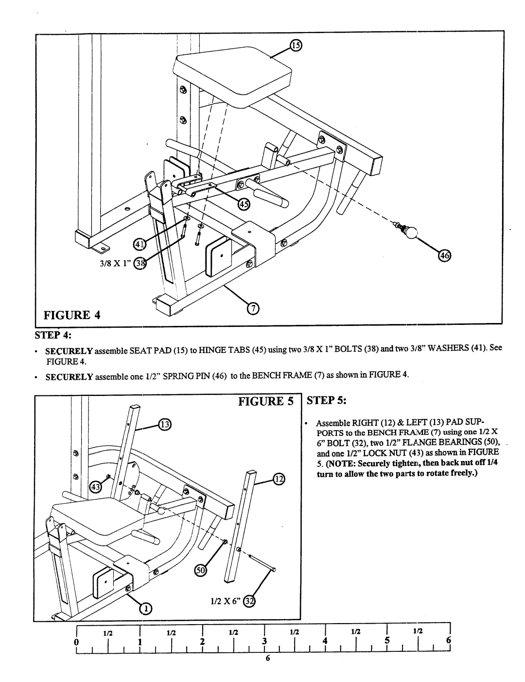
FIGURE 4
STEP 4:
¯SECURELYassemble SEATPAD(15) to HINGETABS(45) using two 3/8 X 1" BOLTS(38) and two 3/8" WASHERS(41). FIGURE4.
¯SECURELYassemble one. 1/2" SPRINGPIN (46) to the BENCHFRAME(7) as shown in FIGURE
FIGURE 5 STEP5:
Assemble RIGHT(12) & LEI~I" (13) PADSUP- PORTSto the BENCHFtLA~.~IE(7) using one 1/2
6" BOLT(32), two 1/2" lZL.~a'qGEBEARINGS(50), and one 1/2" LOCKNUT(43) as shown in FIGURE
5. (NOTE:Securely tightest, then backnut off 114 turn to allow the twoparts to rotate freely.)
112 X 6" ~
1/2 [ 1/2
I
6