STEP10:
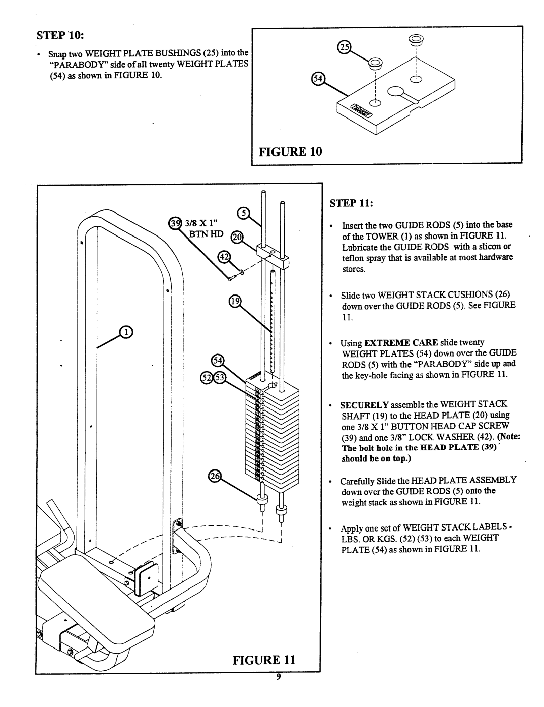
¯Snap two WEIGHTPLATEBUSHINGS(25) into the "PARABODY"side of all twenty WEIGHTPLATES
(54)as shown in FIGURE10.
FIGURE 10
STEP 11:
3/8X 1"
BTNHD ~
Insert the two GUIDERODS(5) into the base of the TOWER(1) as shown in FIGURE11. Lubricate the GUIDERODSwith a sli~n or teflon spray that is available at mosthardware stores.
Slide two WEIGHTSTACKCUSHIONS(26) down over the GUIDERODS(5). See FIGURE 11.
Using EXTREMEC~kRE slide twenty WEIGHTPLATES(54) down over the GUIDE RODS(5) with the "PARABODY"side up and the
SECURELYassemble the WEIGHTSTACK SHAFT(19) to the KEADPLATE(20) using one 3/8 X 1" BLrI~ON ]~IEAD CAP SCREW
(39)and one 3/8" LOCKWASHER(42). (Note: The bolt hole in the ]~E;ADPLATE(39)" should be on top.)
Carefully Slide the HEADPLATEASSEMBLY downover the GUIDERODS(5) onto the weight slack as showrt in FIGURE11.
Apply one set of WEIGHTSTACKLABELS- LBS. ORKGS. (52) (53) to each WEIGHT PLATE(54) as shown in FIGURE11.
FIGURE 11
9
