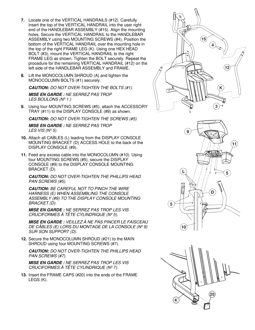
7.Locate one of the VERTICAL HANDRAILS (#12). Carefully insert the top of the VERTICAL HANDRAIL into the user right end of the HANDLEBAR ASSEMBLY (#15). Align the mounting holes. Secure the VERTICAL HANDRAIL to the HANDLEBAR ASSEMBLY using two MOUNTING SCREWS (#4). Position the bottom of the VERTICAL HANDRAIL over the mounting hole in the top of the right FRAME LEG (K). Using one HEX HEAD BOLT (#3), mount the VERTICAL HANDRAIL to the right FRAME LEG as shown. Tighten the BOLT securely. Repeat the procedure for the remaining VERTICAL HANDRAIL (#12) on the left side of the HANDLEBAR ASSEMBLY and FRAME.
8.Lift the MONOCOLUMN SHROUD (A) and tighten the MONOCOLUMN BOLTS (#1) securely.
CAUTION: DO NOT
MISE EN GARDE : NE SERREZ PAS TROP LES BOULONS (Nº 1.)
9.Using four MOUNTING SCREWS (#5), attach the ACCESSORY TRAY (#11) to the DISPLAY CONSOLE (#9) as shown.
CAUTION: DO NOT
MISE EN GARDE : NE SERREZ PAS TROP LES VIS (Nº 5).
10.Attach all CABLES (L) leading from the DISPLAY CONSOLE MOUNTING BRACKET (D) ACCESS HOLE to the back of the DISPLAY CONSOLE (#9).
11.Feed any excess cable into the MONOCOLUMN (#10). Using four MOUNTING SCREWS (#5), secure the DISPLAY CONSOLE (#9) to the DISPLAY CONSOLE MOUNTING BRACKET (D).
CAUTION: DO NOT
15
4
12
K
3
9
11
L | 5 |
|
CAUTION: BE CAREFUL NOT TO PINCH THE WIRE | D |
HARNESS (E) WHEN ASSEMBLING THE CONSOLE | |
ASSEMBLY (#9) TO THE DISPLAY CONSOLE MOUNTING |
|
BRACKET (D). | 5 |
MISE EN GARDE : NE SERREZ PAS TROP LES VIS CRUCIFORMES À TÊTE CYLINDRIQUE (Nº 5).
MISE EN GARDE : VEILLEZ À NE PAS PINCER LE FAISCEAU
DE CÂBLES (E) LORS DU MONTAGE DE LA CONSOLE (Nº 9)10
SUR SON SUPPORT (D).
12.Secure the MONOCOLUMN SHROUD (#21) to the MAIN SHROUD using four MOUNTING SCREWS (#7).
CAUTION: DO NOT
PAN SCREWS (#7).
MISE EN GARDE : NE SERREZ PAS TROP LES VIS
CRUCIFORMES À TÊTE CYLINDRIQUE (Nº 7).
13. Insert the FRAME CAPS (#20) into the ends of the FRAME LEGS (K).
20
K
