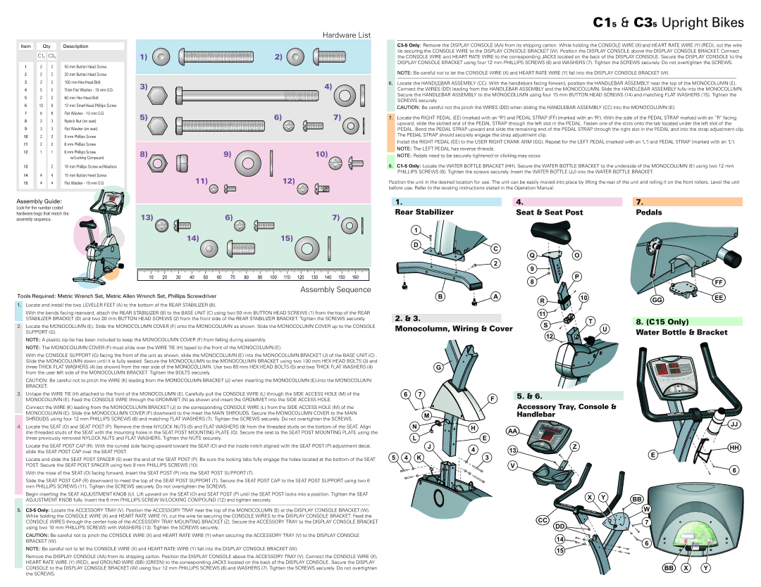
Hardware List
C15 & C35 Upright Bikes
Item | Qty | Description | |
| C15 | C35 |
|
1 | 2 | 2 | 50 mm Button Head Screw |
2 | 2 | 2 | 20 mm Button Head Screw |
3 | 2 | 2 | 100 mm Hex Head Bolt |
4 | 5 | 5 | Thick Flat Washer - 16 mm O.D. |
5 | 2 | 2 | 60 mm Hex Head Bolt |
6 | 10 | 8 | 12 mm Small Head Phillips Screw |
7 | 8 | 8 | Flat Washer - 12 mm O.D. |
8 | 3 | 3 | Nylock Nut (on seat) |
9 | 3 | 3 | Flat Washer (on seat) |
10 | 2 | 2 | 8 mm Phillips Screw |
11 | 2 | 2 | 6 mm Phillips Screw |
12 | 1 | 1 | 6 mm Phillips Screw |
|
|
| w/Locking Compound |
13 |
| 2 | 10 mm Phillips Screw w/Washers |
14 | 4 | 4 | 15 mm Button Head Screw |
15 | 4 | 4 | Flat Washer - 18 mm O.D. |
Assembly Guide:
Look for the number coded hardware bags that match the assembly sequence.
1)
3)
5)
8)
13)
9)
11)
6)
14)
2)
4)
6)7)
10)
12)
7) ![]()
15)
NOTE: Be careful not to let the CONSOLE WIRE (X) and HEART RATE WIRE (Y) fall into the DISPLAY CONSOLE BRACKET (W).
6.Locate the HANDLEBAR ASSEMBLY (CC). With the handlebars facing forward, position the HANDLEBAR ASSEMBLY near the top of the MONOCOLUMN (E). Connect the WIRES (DD) leading from the HANDLEBAR ASSEMBLY and the MONOCOLUMN. Slide the HANDLEBAR ASSEMBLY fully into the MONOCOLUMN. Secure the HANDLEBAR ASSEMBLY to the MONOCOLUMN using four 15 mm BUTTON HEAD SCREWS (14) and matching FLAT WASHERS (15). Tighten the SCREWS securely.
CAUTION: Be careful not the pinch the WIRES (DD) when sliding the HANDLEBAR ASSEMBLY (CC) into the MONOCOLUMN (E).
7.Locate the RIGHT PEDAL (EE) (marked with an "R") and PEDAL STRAP (FF) (marked with an "R"). With the side of the PEDAL STRAP marked with an “R” facing upward, slide the slotted end of the PEDAL STRAP through the left slot in the PEDAL. Fasten one of the slots onto the tab located under the left slot of the PEDAL. Bend the PEDAL STRAP upward and slide the remaining end of the PEDAL STRAP through the right slot in the PEDAL and into the strap adjustment clip. The PEDAL STRAP should securely engage the strap adjustment clip.
Install the RIGHT PEDAL (EE) to the USER RIGHT CRANK ARM (GG). Repeat for the LEFT PEDAL (marked with an "L") and PEDAL STRAP (marked with an "L"). NOTE: The LEFT PEDAL has reverse threads.
NOTE: Pedals need to be securely tightened or clicking may occur.
8.
Position the unit in the desired location for use. The unit can be easily moved into place by lifting the rear of the unit and rolling it on the front rollers. Level the unit before use. Refer to the leveling instructions stated in the Operation Manual.
1. | 4. |
| 7. |
Rear Stabilizer | Seat & Seat Post | Pedals | |
1 |
|
|
|
D | C |
|
|
|
|
| |
| Q | O |
|
| 2 |
|
|
| 9 |
|
|
10 | 20 | 30 | 40 | 50 | 60 | 70 | 80 | 90 | 100 | 110 | 120 | 130 | 140 | 150 | 160 |
Assembly Sequence
Tools Required: Metric Wrench Set, Metric Allen Wrench Set, Phillips Screwdriver
1.Locate and install the two LEVELER FEET (A) to the bottom of the REAR STABILIZER (B).
With the bends facing rearward, attach the REAR STABILIZER (B) to the BASE UNIT (C) using two 50 mm BUTTON HEAD SCREWS (1) from the top of the REAR STABILIZER BRACKET (D) and two 20 mm BUTTON HEAD SCREWS (2) from the front side of the REAR STABILIZER BRACKET. Tighten the SCREWS securely.
2.Locate the MONOCOLUMN (E). Slide the MONOCOLUMN COVER (F) onto the MONOCOLUMN as shown. Slide the MONOCOLUMN COVER up to the CONSOLE SUPPORT (G).
NOTE: A plastic
NOTE: The MONOCOLUMN COVER (F) must slide over the WIRE TIE (H) taped to the front of the MONOCOLUMN (E).
With the CONSOLE SUPPORT (G) facing the front of the unit as shown, slide the MONOCOLUMN (E) into the MONOCOLUMN BRACKET (J) of the BASE UNIT (C) . Slide the MONOCOLUMN down until it is fully seated. Secure the MONOCOLUMN to the MONOCOLUMN BRACKET using two 100 mm HEX HEAD BOLTS (3) and three THICK FLAT WASHERS (4) (as shown) from the rear side of the MONOCOLUMN. Use two 60 mm HEX HEAD BOLTS (5) and two THICK FLAT WASHERS (4) from the user left side of the MONOCOLUMN BRACKET. Tighten the BOLTS securely.
CAUTION: Be careful not to pinch the WIRE (K) leading from the MONOCOLUMN BRACKET (J) when inserting the MONOCOLUMN (E) into the MONOCOLUMN BRACKET.
3.Untape the WIRE TIE (H) attached to the front of the MONOCOLUMN (E). Carefully pull the CONSOLE WIRE (L) through the SIDE ACCESS HOLE (M) of the MONOCOLUMN (E). Feed the CONSOLE WIRE through the GROMMET (N) as shown and insert the GROMMET into the SIDE ACCESS HOLE.
Connect the WIRE (K) leading from the MONOCOLUMN BRACKET (J) to the corresponding CONSOLE WIRE (L) from the SIDE ACCESS HOLE (M) of the MONOCOLUMN (E). Slide the MONOCOLUMN COVER (F) downward to the meet the MAIN SHROUDS. Secure the MONOCOLUMN COVER to the MAIN SHROUDS using four 12 mm PHILLIPS SCREWS (6) and matching FLAT WASHERS (7). Tighten the SCREWS securely. Do not overtighten the SCREWS.
4.Locate the SEAT (O) and SEAT POST (P). Remove the three NYLOCK NUTS (8) and FLAT WASHERS (9) from the threaded studs on the bottom of the SEAT. Align the threaded studs of the SEAT with the mounting holes in the SEAT POST MOUNTING PLATE (Q). Secure the seat to the SEAT POST MOUNTING PLATE using the three previously removed NYLOCK NUTS and FLAT WASHERS. Tighten the NUTS securely.
Locate the SEAT POST CAP (R). With the curved side facing upward toward the SEAT (O) and the inside notch aligned with the SEAT POST (P) adjustment decal, slide the SEAT POST CAP over the SEAT POST.
Locate and slide the SEAT POST SPACER (S) over the end of the SEAT POST (P). Be sure the locking tabs fully engage the holes located at the bottom of the SEAT POST. Secure the SEAT POST SPACER using two 8 mm PHILLIPS SCREWS (10).
With the nose of the SEAT (O) facing forward, insert the SEAT POST (P) into the SEAT POST SUPPORT (T).
Slide the SEAT POST CAP (R) downward to meet the top of the SEAT POST SUPPORT (T). Secure the SEAT POST CAP to the SEAT POST SUPPORT using two 6 mm PHILLIPS SCREWS (11). Tighten the SCREWS securely. Do not overtighten the SCREWS.
Begin inserting the SEAT ADJUSTMENT KNOB (U). Lift upward on the SEAT (O) and SEAT POST (P) until the SEAT POST locks into a position. Tighten the SEAT ADJUSTMENT KNOB fully. Insert the 6 mm PHILLIPS SCREW W/LOCKING COMPOUND (12) and tighten securely.
5.
CAUTION: Be careful not to pinch the CONSOLE WIRE (X) and HEART RATE WIRE (Y) when securing the ACCESSORY TRAY (V) to the DISPLAY CONSOLE BRACKET (W).
NOTE: Be careful not to let the CONSOLE WIRE (X) and HEART RATE WIRE (Y) fall into the DISPLAY CONSOLE BRACKET (W).
Remove the DISPLAY CONSOLE (AA) from its shipping carton. Position the DISPLAY CONSOLE above the ACCESSORY TRAY (V). Connect the CONSOLE WIRE (X), HEART RATE WIRE (Y) (RED), and GROUND WIRE (BB) (GREEN) to the corresponding JACKS located on the back of the DISPLAY CONSOLE. Secure the DISPLAY CONSOLE to the DISPLAY CONSOLE BRACKET (W) using four 12 mm PHILLIPS SCREWS (6) and WASHERS (7). Tighten the SCREWS securely. Do not overtighten the SCREWS.
|
|
| P |
|
|
|
|
| 8 |
|
|
| FF |
B | A | R | 10 |
| GG | EE |
|
|
|
|
| ||
2. & 3. |
| 11 |
|
|
|
|
|
| T |
| 8. (C15 Only) |
| |
Monocolumn, Wiring & Cover | S |
|
| |||
| U |
|
| |||
|
| Water Bottle & Bracket | ||||
|
| 12 |
|
| ||
|
|
|
|
|
| |
G
6 | 7 |
|
| F |
| 5. & 6. |
|
|
|
|
|
|
| ||
|
|
|
|
|
| Accessory Tray, Console & |
|
|
| M |
|
|
| Handlebar |
|
| N |
| H |
|
|
| JJ |
|
|
| AA |
| |||
|
|
|
|
| |||
|
|
|
|
|
| ||
| L |
|
| E |
|
|
|
|
| J | 4 |
| 13 | Z | HH |
|
|
|
|
| E | ||
5 4 | K |
|
| 3 |
|
| |
|
|
|
|
| |||
|
|
|
|
| V |
| 6 |
|
|
|
|
|
|
| |
X | Y | BB |
|
|
W
CC |
| 7 |
| DD | |
|
| |
| 14 | 6 |
|
| |
| 15 |
|