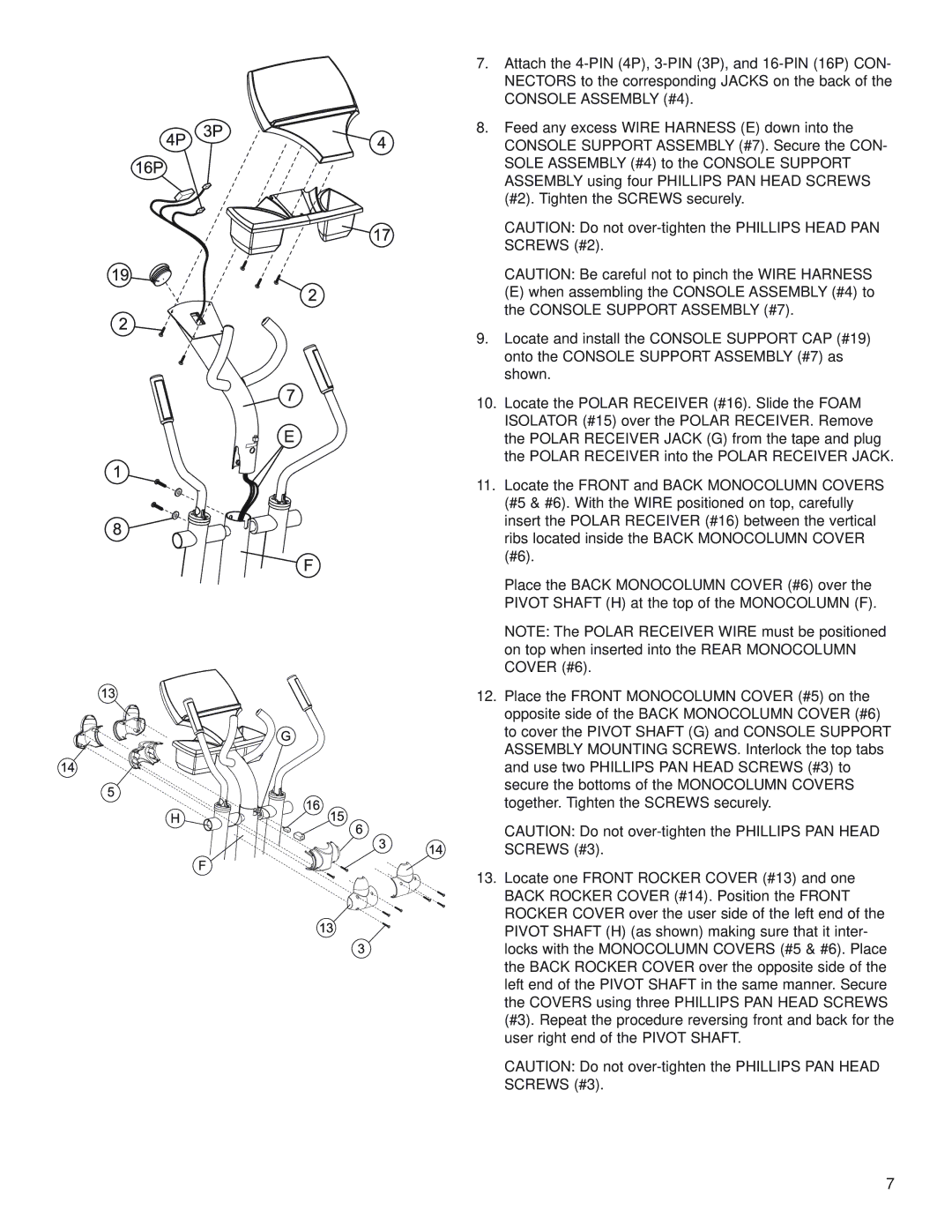
7.Attach the
8.Feed any excess WIRE HARNESS (E) down into the CONSOLE SUPPORT ASSEMBLY (#7). Secure the CON- SOLE ASSEMBLY (#4) to the CONSOLE SUPPORT ASSEMBLY using four PHILLIPS PAN HEAD SCREWS (#2). Tighten the SCREWS securely.
CAUTION: Do not
CAUTION: Be careful not to pinch the WIRE HARNESS
(E) when assembling the CONSOLE ASSEMBLY (#4) to the CONSOLE SUPPORT ASSEMBLY (#7).
9.Locate and install the CONSOLE SUPPORT CAP (#19) onto the CONSOLE SUPPORT ASSEMBLY (#7) as shown.
10.Locate the POLAR RECEIVER (#16). Slide the FOAM ISOLATOR (#15) over the POLAR RECEIVER. Remove the POLAR RECEIVER JACK (G) from the tape and plug the POLAR RECEIVER into the POLAR RECEIVER JACK.
11.Locate the FRONT and BACK MONOCOLUMN COVERS (#5 & #6). With the WIRE positioned on top, carefully insert the POLAR RECEIVER (#16) between the vertical ribs located inside the BACK MONOCOLUMN COVER (#6).
Place the BACK MONOCOLUMN COVER (#6) over the PIVOT SHAFT (H) at the top of the MONOCOLUMN (F).
NOTE: The POLAR RECEIVER WIRE must be positioned on top when inserted into the REAR MONOCOLUMN COVER (#6).
12.Place the FRONT MONOCOLUMN COVER (#5) on the opposite side of the BACK MONOCOLUMN COVER (#6) to cover the PIVOT SHAFT (G) and CONSOLE SUPPORT ASSEMBLY MOUNTING SCREWS. Interlock the top tabs and use two PHILLIPS PAN HEAD SCREWS (#3) to secure the bottoms of the MONOCOLUMN COVERS together. Tighten the SCREWS securely.
CAUTION: Do not
13.Locate one FRONT ROCKER COVER (#13) and one BACK ROCKER COVER (#14). Position the FRONT ROCKER COVER over the user side of the left end of the PIVOT SHAFT (H) (as shown) making sure that it inter- locks with the MONOCOLUMN COVERS (#5 & #6). Place the BACK ROCKER COVER over the opposite side of the left end of the PIVOT SHAFT in the same manner. Secure the COVERS using three PHILLIPS PAN HEAD SCREWS (#3). Repeat the procedure reversing front and back for the user right end of the PIVOT SHAFT.
CAUTION: Do not
7
