16 |
|
|
|
|
|
|
| 2 |
|
|
|
|
|
| 1 |
|
|
| 19 |
|
|
|
|
|
|
|
| 11 3/8 X | |
| 19 | 8 |
| 19 |
|
|
|
| 18 |
| |
|
|
|
|
| |
|
|
|
| 12 3/8 X 3” |
|
|
| 3 |
|
|
|
|
|
| 19 |
|
|
|
|
|
| 9 |
|
|
|
|
| 12 | 3/8 X 3” |
19 |
|
|
|
| 18 |
|
|
|
|
| |
13 |
| 15 | 14 |
|
|
|
|
|
| ||
|
|
| 11 | 3/8 X |
|
|
|
| 18 |
| |
FIGURE 1 |
|
|
|
|
|
STEP 1: |
|
|
|
|
|
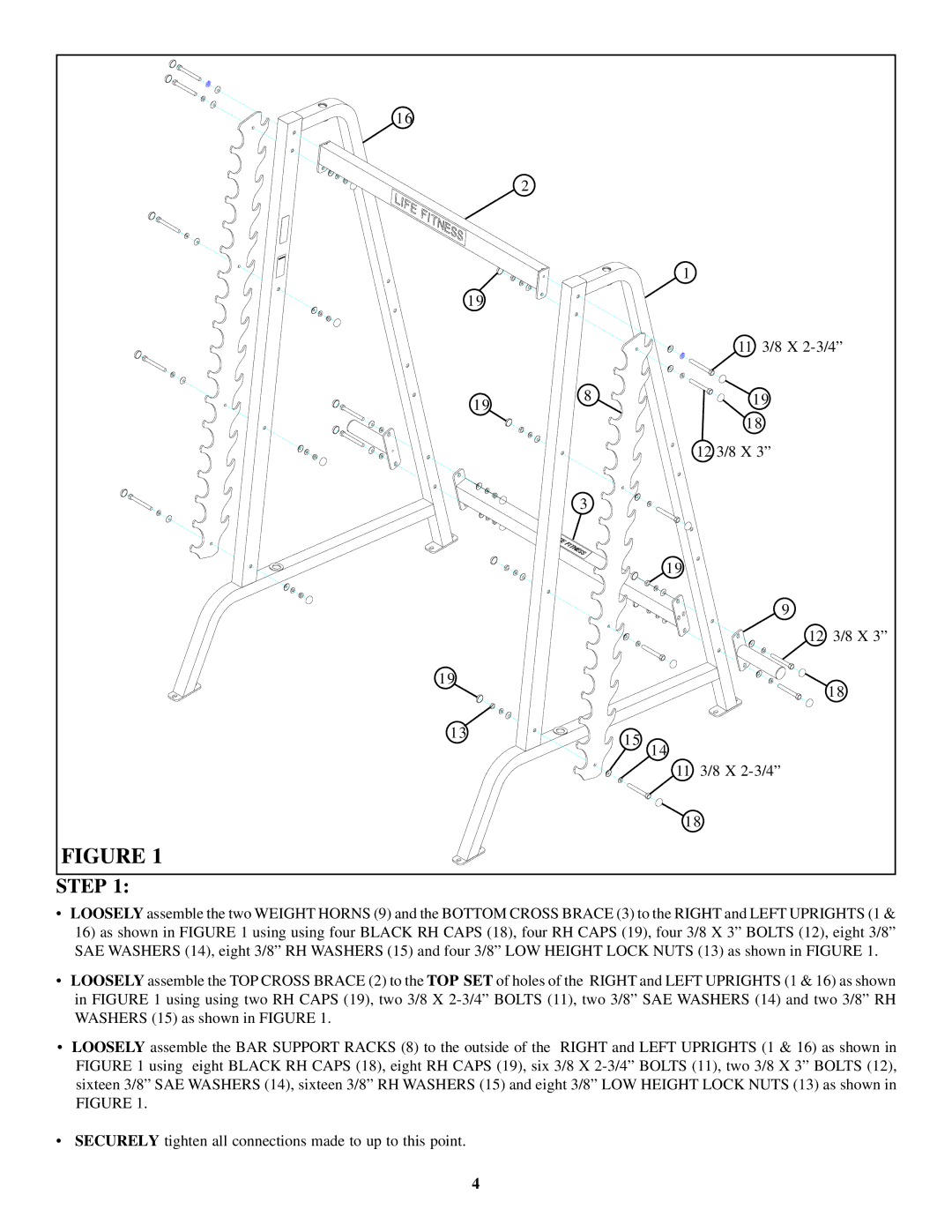
•LOOSELY assemble the two WEIGHT HORNS (9) and the BOTTOM CROSS BRACE (3) to the RIGHT and LEFT UPRIGHTS (1 & 16) as shown in FIGURE 1 using using four BLACK RH CAPS (18), four RH CAPS (19), four 3/8 X 3” BOLTS (12), eight 3/8” SAE WASHERS (14), eight 3/8” RH WASHERS (15) and four 3/8” LOW HEIGHT LOCK NUTS (13) as shown in FIGURE 1.
•LOOSELY assemble the TOP CROSS BRACE (2) to the TOP SET of holes of the RIGHT and LEFT UPRIGHTS (1 & 16) as shown in FIGURE 1 using using two RH CAPS (19), two 3/8 X
•LOOSELY assemble the BAR SUPPORT RACKS (8) to the outside of the RIGHT and LEFT UPRIGHTS (1 & 16) as shown in FIGURE 1 using eight BLACK RH CAPS (18), eight RH CAPS (19), six 3/8 X
•SECURELY tighten all connections made to up to this point.
4
