Smith Machine PL06 Unpacking & Assembly Instructions
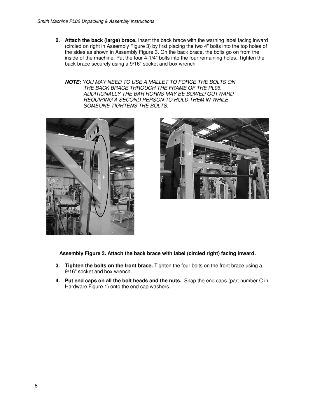
2.Attach the back (large) brace. Insert the back brace with the warning label facing inward (circled on right in Assembly Figure 3) by first placing the two 4” bolts into the top holes of the sides as shown in Assembly Figure 3. On the back brace, the bolts go on from the inside of the machine. Put the four
NOTE: YOU MAY NEED TO USE A MALLET TO FORCE THE BOLTS ON THE BACK BRACE THROUGH THE FRAME OF THE PL06. ADDITIONALLY THE BAR HORNS MAY BE BOWED OUTWARD REQUIRING A SECOND PERSON TO HOLD THEM IN WHILE SOMEONE TIGHTENS THE BOLTS.
Assembly Figure 3. Attach the back brace with label (circled right) facing inward.
3.Tighten the bolts on the front brace. Tighten the four bolts on the front brace using a 9/16” socket and box wrench.
4.Put end caps on all the bolt heads and the nuts. Snap the end caps (part number C in Hardware Figure 1) onto the end cap washers.
8