SM80 Unpacking & Assembly Instructions
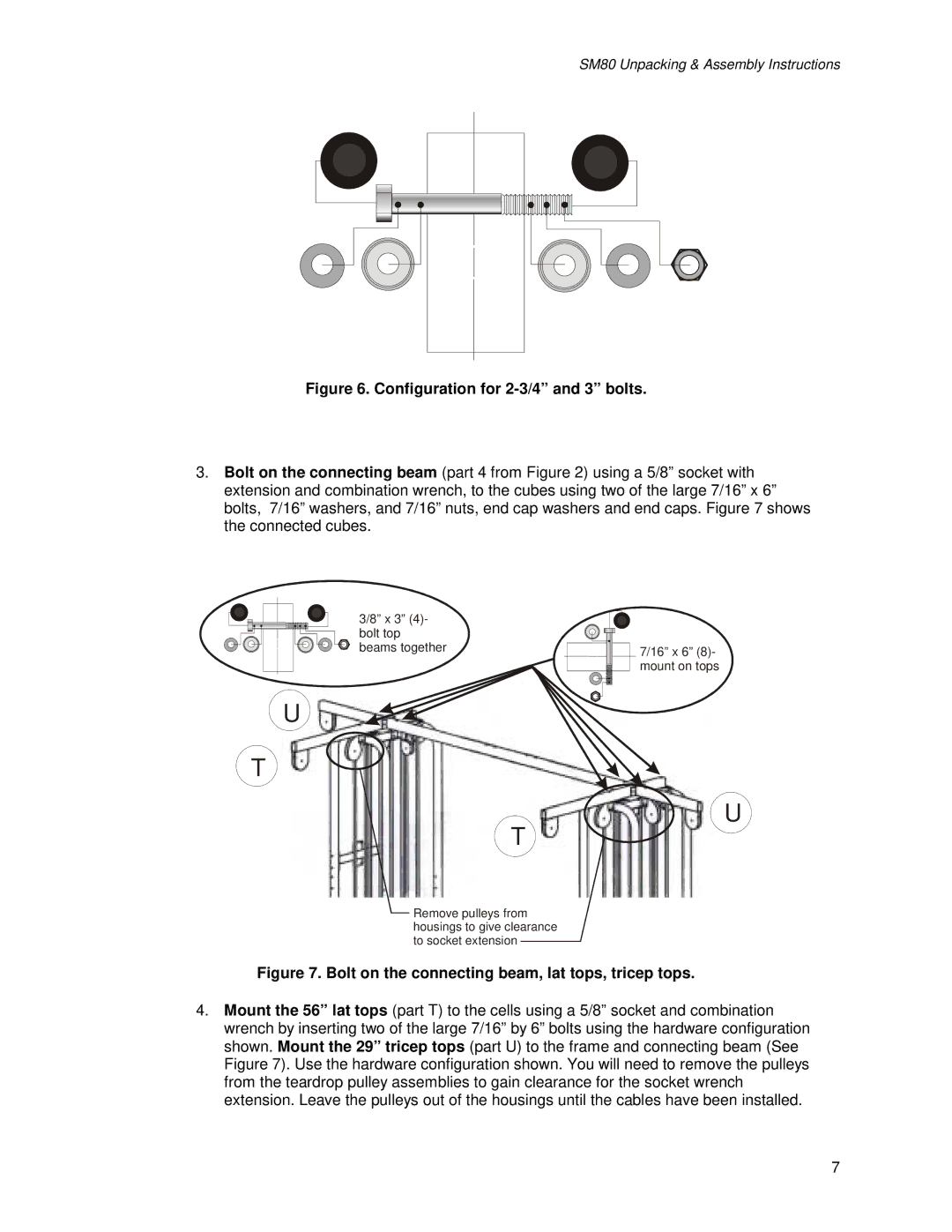
Figure 6. Configuration for 2-3/4” and 3” bolts.
3.Bolt on the connecting beam (part 4 from Figure 2) using a 5/8” socket with extension and combination wrench, to the cubes using two of the large 7/16” x 6” bolts, 7/16” washers, and 7/16” nuts, end cap washers and end caps. Figure 7 shows the connected cubes.
3/8” x 3” (4)- bolt top beams together
U
T
T
Remove pulleys from housings to give clearance to socket extension
7/16” x 6” (8)- mount on tops
U
Figure 7. Bolt on the connecting beam, lat tops, tricep tops.
4.Mount the 56” lat tops (part T) to the cells using a 5/8” socket and combination wrench by inserting two of the large 7/16” by 6” bolts using the hardware configuration shown. Mount the 29” tricep tops (part U) to the frame and connecting beam (See Figure 7). Use the hardware configuration shown. You will need to remove the pulleys from the teardrop pulley assemblies to gain clearance for the socket wrench extension. Leave the pulleys out of the housings until the cables have been installed.
7