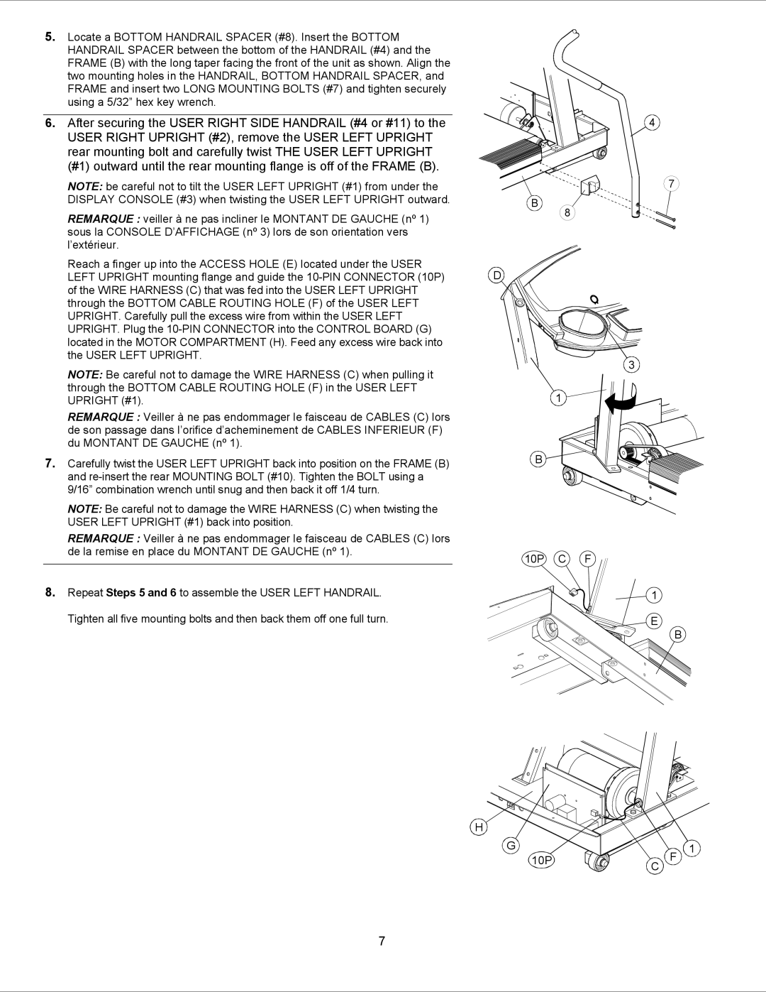
5. Locate a BOTTOM HANDRAIL SPACER (#8). Insert the BOTTOM |
HANDRAIL SPACER between the bottom of the HANDRAIL (#4) and the |
FRAME (B) with the long taper facing the front of the unit as shown. Align the |
two mounting holes in the HANDRAIL, BOTTOM HANDRAIL SPACER, and |
FRAME and insert two LONG MOUNTING BOLTS (#7) and tighten securely |
using a 5/32” hex key wrench. |
6. After securing the USER RIGHT SIDE HANDRAIL (#4 or #11) to the |
USER RIGHT UPRIGHT (#2), remove the USER LEFT UPRIGHT |
rear mounting bolt and carefully twist THE USER LEFT UPRIGHT |
(#1) outward until the rear mounting flange is off of the FRAME (B). |
NOTE: be careful not to tilt the USER LEFT UPRIGHT (#1) from under the |
DISPLAY CONSOLE (#3) when twisting the USER LEFT UPRIGHT outward. |
REMARQUE : veiller à ne pas incliner le MONTANT DE GAUCHE (nº 1) |
sous la CONSOLE D’AFFICHAGE (nº 3) lors de son orientation vers |
l’extérieur. |
Reach a finger up into the ACCESS HOLE (E) located under the USER |
LEFT UPRIGHT mounting flange and guide the |
of the WIRE HARNESS (C) that was fed into the USER LEFT UPRIGHT |
through the BOTTOM CABLE ROUTING HOLE (F) of the USER LEFT |
UPRIGHT. Carefully pull the excess wire from within the USER LEFT |
UPRIGHT. Plug the |
located in the MOTOR COMPARTMENT (H). Feed any excess wire back into |
the USER LEFT UPRIGHT. |
NOTE: Be careful not to damage the WIRE HARNESS (C) when pulling it |
through the BOTTOM CABLE ROUTING HOLE (F) in the USER LEFT |
B
D
8
4
7
3
UPRIGHT (#1). |
REMARQUE : Veiller à ne pas endommager le faisceau de CABLES (C) lors |
de son passage dans l’orifice d’acheminement de CABLES INFERIEUR (F) |
du MONTANT DE GAUCHE (nº 1). |
7. Carefully twist the USER LEFT UPRIGHT back into position on the FRAME (B) |
and |
9/16” combination wrench until snug and then back it off 1/4 turn. |
NOTE: Be careful not to damage the WIRE HARNESS (C) when twisting the |
USER LEFT UPRIGHT (#1) back into position. |
REMARQUE : Veiller à ne pas endommager le faisceau de CABLES (C) lors |
de la remise en place du MONTANT DE GAUCHE (nº 1). |
8. Repeat Steps 5 and 6 to assemble the USER LEFT HANDRAIL. |
Tighten all five mounting bolts and then back them off one full turn. |
1
B
10P C F
H
G
10P
1
E
C
B
F 1
7
