Air Duct Design and Installation
A well designed and installed ducting system will allow the HRV to operate at its maximum efficiency.
Always try to keep duct runs as short and straight as pos- sible. See Installation Diagrams for various installation options.
The inner and outer liners of the flexible insulated duct must be clamped to the sleeve of the weather hoods (as close to the outside as possible) and the appropriate port on the HRV. It is very important that the fresh air intake line be given special attention to make sure it is well sealed. A good bead of high quality caulking (preferably
silicone sealant) will seal the inner flexible duct to both the HRV port and the weather hood prior to clamping with a large zip tie.
To minimize air flow restriction, the flexible insulated duct that connects the two outside weather hoods to the HRV should be stretched tightly and be as short as possible.
Twisting or folding the duct will severely restrict air flow. See below for the recommended connection of flexible insulated ducts to the the outside weather hoods and the HRV.
![]() WARNING
WARNING
Include a short length of fabric flex duct or other
Stale Air Exhaust System
The stale air exhaust system is accomplished by the posi- tive pressure created in the furnace ducting. The air
handler blower must be running for this system to be effective.
Drain Connection (HRV Only)
During a defrost cycle, the HRV may produce some con- densation. This water should flow into a nearby drain, or be taken away by a condensate pump.
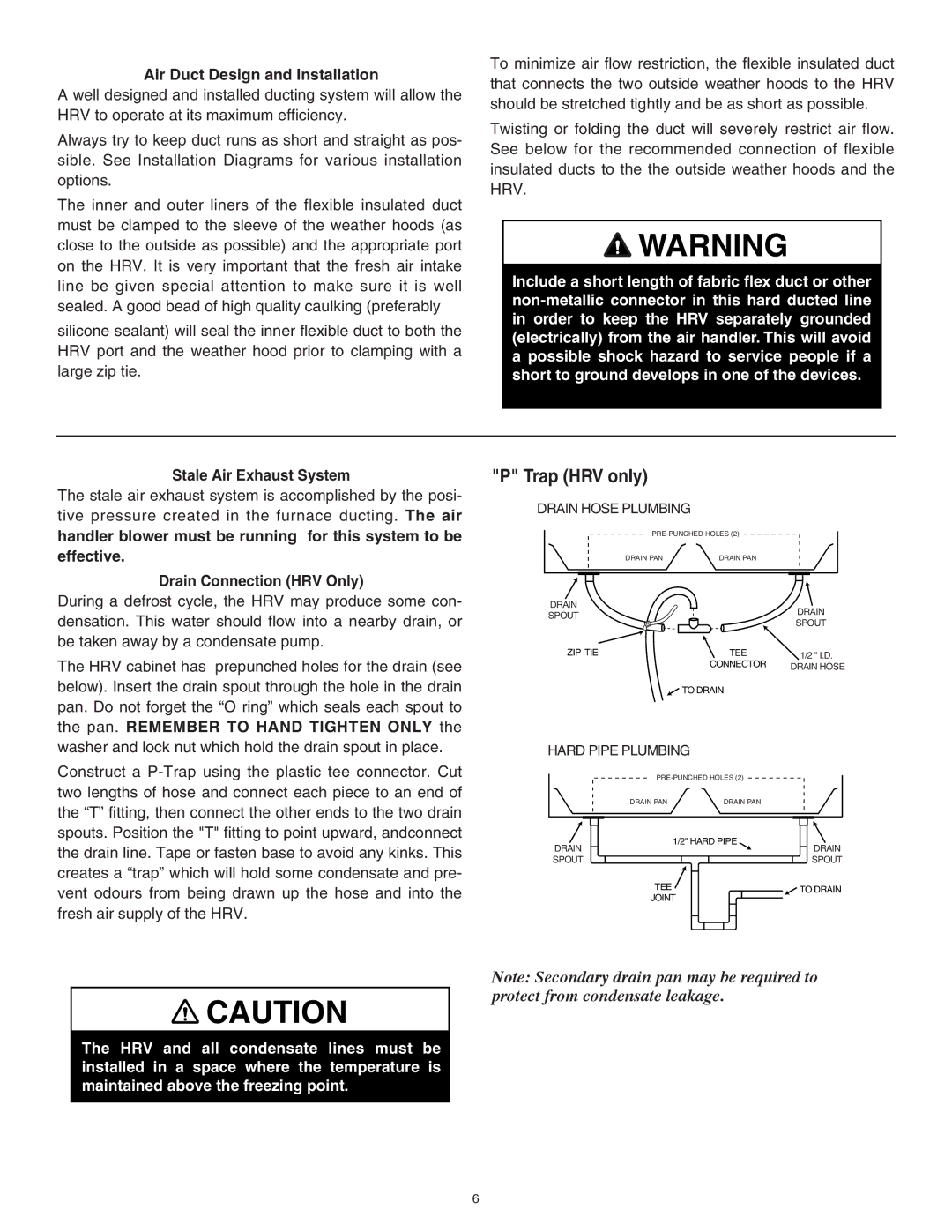
The HRV cabinet has prepunched holes for the drain (see below). Insert the drain spout through the hole in the drain pan. Do not forget the “O ring” which seals each spout to the pan. REMEMBER TO HAND TIGHTEN ONLY the washer and lock nut which hold the drain spout in place.
Construct a
"P" Trap (HRV only)
DRAIN HOSE PLUMBING
| ||
DRAIN PAN | DRAIN PAN |
|
DRAIN |
| DRAIN |
SPOUT |
| |
| SPOUT | |
|
| |
ZIP TIE | TEE | 1/2 " I.D. |
| CONNECTOR | DRAIN HOSE |
![]() TO DRAIN
TO DRAIN
HARD PIPE PLUMBING
DRAIN PANDRAIN PAN
DRAIN | 1/2" HARD PIPE | DRAIN |
| ||
SPOUT |
| SPOUT |
| TEE | TO DRAIN |
| JOINT | |
|
|
![]() CAUTION
CAUTION
The HRV and all condensate lines must be installed in a space where the temperature is maintained above the freezing point.
Note: Secondary drain pan may be required to protect from condensate leakage.
6