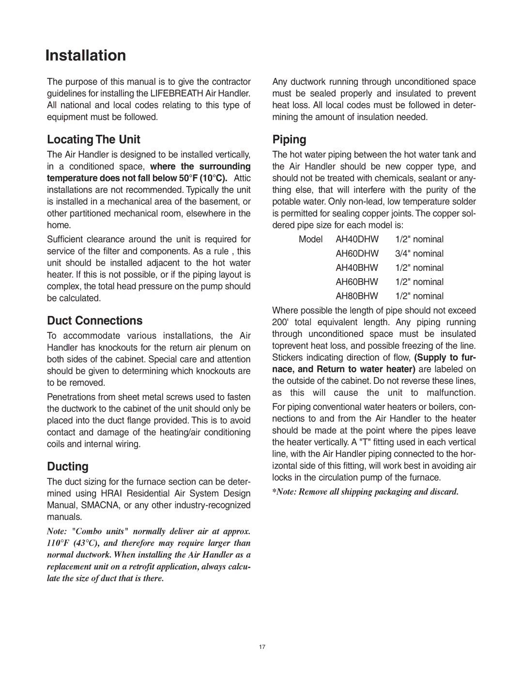
AH60BHW, AH80BHW, AH40BHW, AH40DHW, AH60DHW specifications
Lifebreath is a recognized leader in energy recovery ventilation systems, and its line of products, including the AH60BHW, AH40BHW, AH40DHW, and AH80BHW models, reflects the company's commitment to delivering high-quality indoor air solutions. These models provide an innovative approach to enhancing indoor air quality while ensuring energy efficiency.The Lifebreath AH60BHW model is designed to meet the demands of larger spaces, offering a remarkable airflow capacity. This system incorporates advanced energy recovery technology, enabling it to efficiently transfer heat and moisture between incoming and outgoing air streams. As a result, it maintains comfortable indoor conditions regardless of the external climate, ensuring optimal performance year-round.
For medium-sized areas, the AH40BHW and AH40DHW models are excellent choices. Both systems feature similar designs with slight variations in their configurations. The AH40BHW operates using hot water, making it particularly effective in radiant heating applications. In contrast, the AH40DHW relies on direct water heating, providing reliable and consistent heat distribution. These models also boast high-efficiency filtration systems that capture airborne pollutants, contributing to healthier indoor environments.
The Lifebreath AH80BHW is tailored for extensive applications, delivering superior ventilation and energy management. It utilizes a robust heat recovery core that maximizes energy savings and ensures minimal heat loss during the exchange process. Additionally, the AH80BHW's compact design makes it versatile for various installation scenarios, whether in residential settings or commercial spaces.
All models are equipped with user-friendly controls that allow easy adjustments of airflow settings to suit specific requirements. Furthermore, the addition of advanced monitoring technology ensures that users can track system performance and energy usage, optimizing efficiency. With quiet operation characteristics, these systems enhance comfort without disruptive noise.
Overall, Lifebreath's AH series ventilation systems represent a combination of cutting-edge technology and practical design. Their focus on energy recovery, high filtration efficiency, and user-friendly operation makes them an ideal choice for anyone seeking better air quality and comfort in their indoor spaces. Whether for residential or commercial needs, Lifebreath provides reliable solutions that prioritize both health and efficiency.
