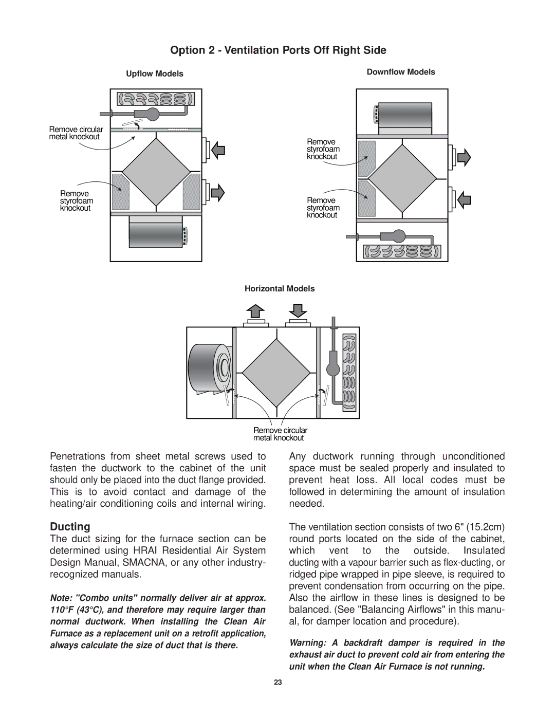
Option 2 - Ventilation Ports Off Right Side
Upflow Models
Remove circular metal knockout
Remove styrofoam knockout
Downflow Models
Remove styrofoam knockout
Remove styrofoam knockout
Horizontal Models
Remove circular metal knockout
Penetrations from sheet metal screws used to fasten the ductwork to the cabinet of the unit should only be placed into the duct flange provided. This is to avoid contact and damage of the heating/air conditioning coils and internal wiring.
Ducting
The duct sizing for the furnace section can be determined using HRAI Residential Air System Design Manual, SMACNA, or any other industry- recognized manuals.
Note: "Combo units" normally deliver air at approx. 110°F (43°C), and therefore may require larger than normal ductwork. When installing the Clean Air Furnace as a replacement unit on a retrofit application, always calculate the size of duct that is there.
Any ductwork running through unconditioned space must be sealed properly and insulated to prevent heat loss. All local codes must be followed in determining the amount of insulation needed.
The ventilation section consists of two 6" (15.2cm) round ports located on the side of the cabinet, which vent to the outside. Insulated ducting with a vapour barrier such as
Warning: A backdraft damper is required in the exhaust air duct to prevent cold air from entering the unit when the Clean Air Furnace is not running.
23