
1102TM specifications
Lightolier 1102TM is a versatile and innovative lighting solution designed to enhance both residential and commercial environments. This product stands out for its unique combination of performance, efficiency, and aesthetic appeal, making it an exceptional choice for various applications.One of the main features of the Lightolier 1102TM is its superior lighting quality. The fixture utilizes advanced LED technology, providing bright and uniform illumination that effectively enhances visibility in any setting. The high Color Rendering Index (CRI) ensures that colors appear vibrant and true to life, making it ideal for spaces where accurate color representation is vital, such as art galleries or retail stores.
In addition to its impressive lighting capabilities, the Lightolier 1102TM boasts energy-efficient performance. The LED technology not only consumes less power than traditional lighting options but also has a significantly longer lifespan, reducing the need for frequent replacements. This efficiency translates to lower energy bills and a smaller carbon footprint, making it an environmentally friendly choice.
The design of the Lightolier 1102TM is both modern and functional. With a sleek and minimalist aesthetic, this fixture can seamlessly integrate into various interior styles. Its adjustable features allow users to direct light where it is needed the most, providing flexibility for different lighting needs and enhancing the overall functionality of the space.
Another key characteristic of the Lightolier 1102TM is its compatibility with smart lighting systems. It can be easily integrated with existing home automation technologies, allowing users to control their lighting remotely or program schedules to fit their lifestyles. This feature not only adds convenience but also improves energy management.
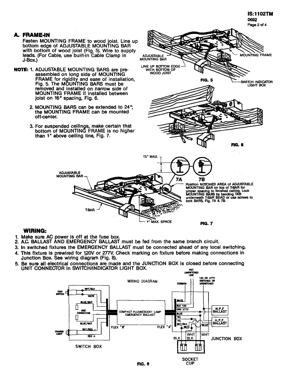
Installation of the Lightolier 1102TM is straightforward, making it accessible for both professional installers and DIY enthusiasts. The fixture is designed to fit a wide range of ceiling types, providing adaptability for various environments.
In summary, the Lightolier 1102TM stands out in the lighting market due to its combination of high-quality illumination, energy efficiency, stylish design, smart technology compatibility, and easy installation. It represents a smart investment for anyone looking to upgrade their lighting solutions while maintaining a focus on sustainability and aesthetic appeal. Whether for home or commercial use, the Lightolier 1102TM is designed to deliver exceptional results.