READ AND UNDERSTAND ALL TRACK, CONNECTOR, FEED-IN-KITS, AND ACCESSORY

INSTRUCTION SHEETS BEFORE INSTALLING ANY PROSPEC™ TRACK ITEM.

This fixture is intended for installation in accordance with the National Electrical Code and local or Federal code specifications. To assure full compliance with codes and regulations, check with your local electrical inspector before installation. To prevent electric shock, turn off electricity at fuse box before proceeding.

Retain these instructions for maintenance reference.

INSTRUCTION SHEET NO.

IS:26650

A0397

Page 1 of 2

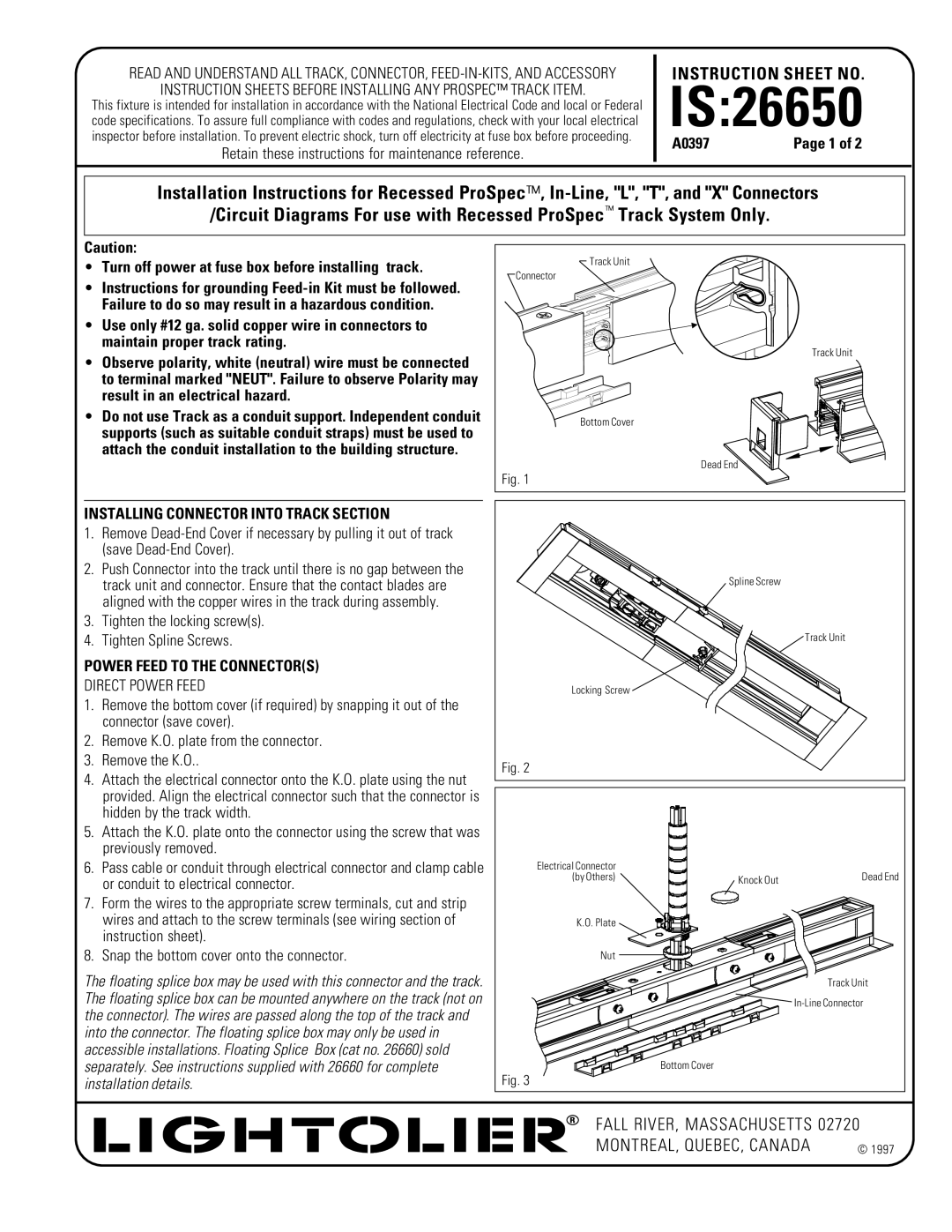
Installation Instructions for Recessed ProSpec, In-Line, "L", "T", and "X" Connectors /Circuit Diagrams For use with Recessed ProSpecTrack System Only.

Caution:

Turn off power at fuse box before installing track.

Instructions for grounding Feed-in Kit must be followed. Failure to do so may result in a hazardous condition.

Use only #12 ga. solid copper wire in connectors to maintain proper track rating.

Observe polarity, white (neutral) wire must be connected to terminal marked "NEUT". Failure to observe Polarity may result in an electrical hazard.

Do not use Track as a conduit support. Independent conduit supports (such as suitable conduit straps) must be used to attach the conduit installation to the building structure.

INSTALLING CONNECTOR INTO TRACK SECTION

1.Remove Dead-End Cover if necessary by pulling it out of track (save Dead-End Cover).

2.Push Connector into the track until there is no gap between the track unit and connector. Ensure that the contact blades are aligned with the copper wires in the track during assembly.

3.Tighten the locking screw(s).

4.Tighten Spline Screws.

POWER FEED TO THE CONNECTOR(S)

DIRECT POWER FEED

1.Remove the bottom cover (if required) by snapping it out of the connector (save cover).

2.Remove K.O. plate from the connector.

3.Remove the K.O..

4.Attach the electrical connector onto the K.O. plate using the nut provided. Align the electrical connector such that the connector is hidden by the track width.

5.Attach the K.O. plate onto the connector using the screw that was previously removed.

6.Pass cable or conduit through electrical connector and clamp cable or conduit to electrical connector.

7.Form the wires to the appropriate screw terminals, cut and strip wires and attach to the screw terminals (see wiring section of instruction sheet).

8.Snap the bottom cover onto the connector.

The floating splice box may be used with this connector and the track. The floating splice box can be mounted anywhere on the track (not on the connector). The wires are passed along the top of the track and into the connector. The floating splice box may only be used in accessible installations. Floating Splice Box (cat no. 26660) sold separately. See instructions supplied with 26660 for complete installation details.

Track Unit

Connector

Track Unit

Bottom Cover

Dead End

Fig. 1

Spline Screw

Track Unit

Locking Screw

Fig. 2

Electrical Connector


(by Others)

Knock Out

Dead End

K.O. Plate


Nut


Track Unit


In-Line Connector


Bottom Cover


Fig. 3


FALL RIVER, MASSACHUSETTS 02720

MONTREAL, QUEBEC, CANADA

© 1997

Page 1
Image 1
Lightolier instruction sheet IS26650, Installing Connector Into Track Section, Power Feed to the Connectors

26650 specifications

The Lightolier 26650 series represents a significant advancement in lighting technology, crafted to meet the diverse needs of both commercial and residential spaces. Known for their innovative design and exceptional performance, the Lightolier 26650 units have gained widespread popularity among architects, interior designers, and consumers alike.

One of the standout features of the Lightolier 26650 is its energy efficiency. Equipped with cutting-edge LED technology, these fixtures consume minimal power while delivering high-quality illumination. This not only reduces electricity bills but also contributes to a lower carbon footprint, making them an environmentally friendly choice. The models in this series often come with various lumen output options, allowing users to select the right brightness based on the specific application.

The Lightolier 26650 also boasts a sleek and modern design, making it suitable for a variety of settings, from offices to retail spaces and even homes. The unobtrusive profile allows these fixtures to blend seamlessly into different architectural styles while providing an aesthetically pleasing solution for lighting needs.

Another key characteristic is the versatility in mounting options. The Lightolier 26650 can be installed in multiple configurations, including recessed, surface-mounted, or pendant styles. This flexibility makes it easier for designers to adapt the lighting to the unique dimensions of a room or the ambiance of a specific area.

The Lightolier 26650 series incorporates advanced technologies such as dimming capabilities and smart controls. Many models are compatible with various dimmer switches, providing users with the ability to adjust brightness levels according to their preferences. Furthermore, integration with smart home systems allows for remote control and scheduling, enhancing convenience and energy management.

Durability is another important aspect, as the Lightolier 26650 is built to withstand demanding environments. The materials used in its construction are designed to resist wear and tear, ensuring longevity and consistent performance. Coupled with a long lifespan typical of LED technology, these fixtures reduce the need for frequent replacements, ultimately saving time and money.

In summary, the Lightolier 26650 series combines energy efficiency, design excellence, versatile mounting options, advanced technologies, and durability. These features not only make it an exceptional choice for effective lighting solutions but also contribute to its growing reputation in the industry. As lighting technology continues to evolve, the Lightolier 26650 stands out as a model of modern innovation, transforming spaces with elegance and functionality.