READ AND UNDERSTAND THESE INSTRUCTIONS BEFORE INSTALLING FIXTURE
This fixture is intended for installation in accordance with the National Electrical Code and local regulations. To assure full compliance with local codes and regulations, check with your local electrical inspector before installation. To prevent electrical shock, turn off electricity at fuse box before proceeding.
Retain these instructions for maintenance reference.
INSTRUCTION SHEET NO.
IS:8292CY
A0400 | Page 1 of 2 |
INSTRUCTIONS FOR THE INSTALLATION AND OPERATION OF PowerArc™ CANOPY FIXTURE
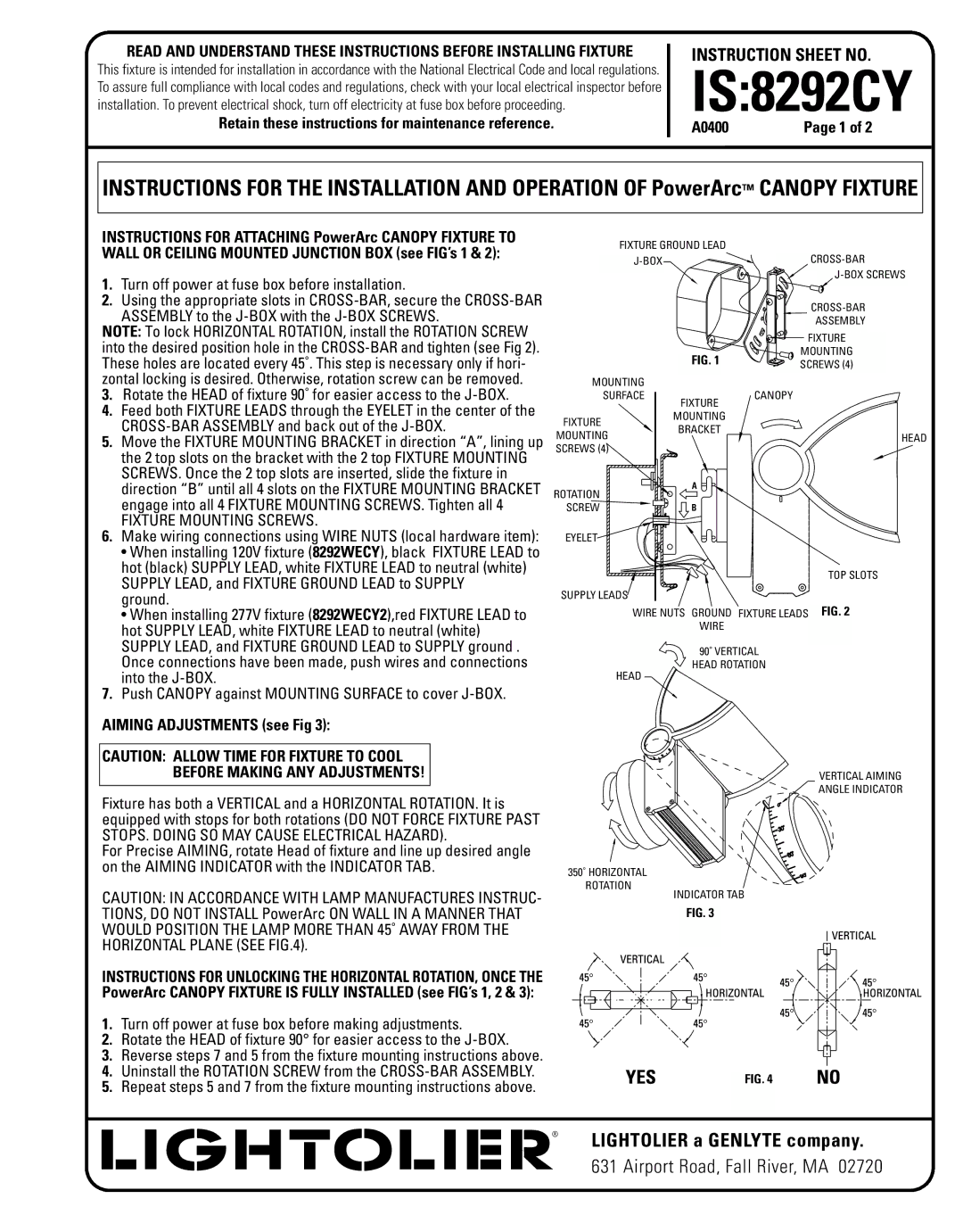
INSTRUCTIONS FOR ATTACHING PowerArc CANOPY FIXTURE TO WALL OR CEILING MOUNTED JUNCTION BOX (see FIG’s 1 & 2):
1.Turn off power at fuse box before installation.
2.Using the appropriate slots in
NOTE: To lock HORIZONTAL ROTATION, install the ROTATION SCREW into the desired position hole in the
3.Rotate the HEAD of fixture 90˚ for easier access to the
4.Feed both FIXTURE LEADS through the EYELET in the center of the
5.Move the FIXTURE MOUNTING BRACKET in direction “A”, lining up the 2 top slots on the bracket with the 2 top FIXTURE MOUNTING SCREWS. Once the 2 top slots are inserted, slide the fixture in direction “B” until all 4 slots on the FIXTURE MOUNTING BRACKET engage into all 4 FIXTURE MOUNTING SCREWS. Tighten all 4
FIXTURE MOUNTING SCREWS.
6.Make wiring connections using WIRE NUTS (local hardware item):
•When installing 120V fixture (8292WECY), black FIXTURE LEAD to hot (black) SUPPLY LEAD, white FIXTURE LEAD to neutral (white) SUPPLY LEAD, and FIXTURE GROUND LEAD to SUPPLY
ground.
•When installing 277V fixture (8292WECY2),red FIXTURE LEAD to hot SUPPLY LEAD, white FIXTURE LEAD to neutral (white) SUPPLY LEAD, and FIXTURE GROUND LEAD to SUPPLY ground . Once connections have been made, push wires and connections into the
7.Push CANOPY against MOUNTING SURFACE to cover
AIMING ADJUSTMENTS (see Fig 3):
CAUTION: ALLOW TIME FOR FIXTURE TO COOL
BEFORE MAKING ANY ADJUSTMENTS!
Fixture has both a VERTICAL and a HORIZONTAL ROTATION. It is equipped with stops for both rotations (DO NOT FORCE FIXTURE PAST STOPS. DOING SO MAY CAUSE ELECTRICAL HAZARD).
For Precise AIMING, rotate Head of fixture and line up desired angle on the AIMING INDICATOR with the INDICATOR TAB.
CAUTION: IN ACCORDANCE WITH LAMP MANUFACTURES INSTRUC- TIONS, DO NOT INSTALL PowerArc ON WALL IN A MANNER THAT WOULD POSITION THE LAMP MORE THAN 45˚ AWAY FROM THE HORIZONTAL PLANE (SEE FIG.4).
INSTRUCTIONS FOR UNLOCKING THE HORIZONTAL ROTATION, ONCE THE PowerArc CANOPY FIXTURE IS FULLY INSTALLED (see FIG’s 1, 2 & 3):
1.Turn off power at fuse box before making adjustments.
2.Rotate the HEAD of fixture 90° for easier access to the
3.Reverse steps 7 and 5 from the fixture mounting instructions above.
4.Uninstall the ROTATION SCREW from the
5.Repeat steps 5 and 7 from the fixture mounting instructions above.
FIXTURE GROUND LEAD
MOUNTING
SURFACE
FIXTURE
MOUNTING
SCREWS (4)
ROTATION
SCREW
EYELET![]()
SUPPLY LEADS![]()
| |
| ASSEMBLY |
| FIXTURE |
FIG. 1 | MOUNTING |
SCREWS (4) | |
FIXTURE | CANOPY |
| |
MOUNTING |
|
BRACKET |
|
HEAD
A
B
TOP SLOTS
WIRE NUTS GROUND FIXTURE LEADS FIG. 2
WIRE
90˚ VERTICAL
HEAD ROTATION
HEAD
VERTICAL AIMING
![]() ANGLE INDICATOR
ANGLE INDICATOR
350˚ HORIZONTAL
ROTATION
INDICATOR TAB
FIG. 3
FIG. 4
® |