Instructions for Installation (cont'd)
Temperature-Pressure Relief Valve
•,WARNING | _,WARNING | I |
At the time of manufacture this water heater was provid- | The | must be manu- |
ed with a combination
maintains periodic inspection of production of listed
equipment or materials, as meeting the requirements for Relief Valves and Automatic Gas Shutoff Devices for Hot
Water Supply Systems, and the latest edition of ANSI Z21.22 and the code requirements of ASME. If replaced, the valve must meet the requirements of local codes, but not less than a combination temperature and pressure relief valve certified as meeting the requirements for Relief Valves and Automatic Gas Shutoff Devices for Hot
Water Supply Systems,ANSI Z21.22 by a nationally recog- nized testing laboratory that maintains periodic inspection of productionof listed equipment or materials.
The valve must be marked with a maximum set pressure not to exceed the marked hydrostaticworking pressureof the water heater (150 Ibs./sq. in.) and a discharge capacity not lessthan the water heater input rate as shown on the model rating plate. (Electric heaters - watts divided by 1000 x 3415 equal BTU/Hr.rate.)
Your local jursdictional authority, while mandating the
use of a
Compliance with such localrequirements must be satisfied by the installer or end user of the water heater with a
Iocallyprescribed
installed in the designated opening in the water heater in place of the factoryfurnishedvalve.
For safe operation of the water heater, the relief valve must not be removed from it'sdesignated opening or plugged.
The
I the relief valve. Positionthe valve downward and provide tubing so that any dischargewill exit only within 6 inches above, or at any distance below the structural floor. Be certain that no contact is made with any live electrical part. The discharqe opening must not be blocked or reduced in size und'erany circumstances.Excessivelength, over 30 feet, or use of more than four elbows can cause restrictionand reducethe dischargecapacity of the valve.
No valve or other obstructionis to be placed between the
relief valve and the tank. Do not connecttubing directly to dischargedrain unlessa 6" air gap is provided. To prevent
bodily injury, hazard to life, or property damage, the relief valve must be allowed to discharge water in quantities should circumstances demand. If the dischargepipe is not connected to a drain or other suitable means, the water
flow may cause property damage.
•Must not be smaller in size than the outlet pipe size of
the valve, or have any reducing couplings or other restrictions.
•Must not be plugged or blocked.
•Must be of material listedfor hot water distribution.
•Must be installed so as to allow complete drainage of both the
•Must terminate at an adequate drain,
•Must not have any valve between the relief valve and tank.
ally operated at least once a year. Caution should be I taken to ensure that (1) no one is in front of or I
around the outlet of the
If after manually operating the valve, it fails to com- pletely reset and continues to release water, immedi- ately close the cold water inlet to the water heater, follow the draining instructions, and replace the
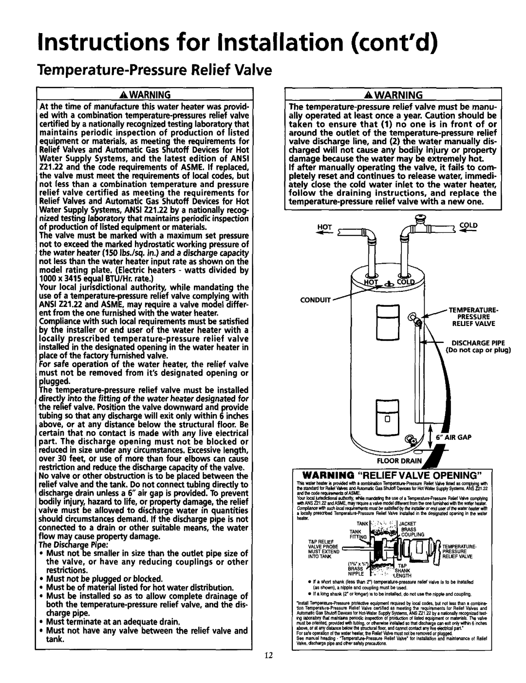
HOTOLD
_ _ [_
,___'_ . r,_
CONDUIT/
(_PRESSURE
RELIEFVALVE
__L _TEMDISCHARGEPER TURE" PIPE
III _ (Do not capor plug)
IRGAP
V4ARNING "RELIEF VALVE OPENING"
_==_=d_V ,0__A*_O__=.GonTe,.SH=W=u_.S_S_R,e,kV_'N=I__.'*=_=*__ ,_o_, _¢_A,_fQE.
Your _:alc°°ejul_de_Joiledty, whilemandal_gfile useof a Temperaturs_essareRsl_efWivecomping
_hANBZ21_2andASME.ma_qureavalvem0eqldhf_'e_tl_nthe0n
c_=_,_=_,_,_,,_,_,_
a locallypre_
_"_ | TANK ;1' /_,h !: | JACKET | |
| |||
| TANK | BRASS | |
| F._ G |
| COUPLING |
VALVE PROBE |
|
| TEMPERATURE- |
MUST EXTEND |
|
| PRESSURE |
INTO TANK | = |
| RELIEF VALVE |
| _RA_B |
| S_ |
•_f a short shank (/e=,,sthan 2"1
I_eshown),anippleandcouplingmustbeused
• Ifalongshank(2'orfo_jer)isdotobeinstuset_bellbenip,p_eandcoupling.
"ln_l
_g is_oratpffthat men_m _I_ inseq_onP_p_ offinal equipmentor marian, Thevafw
_beo.nt_,_o_deq*_,,_,_o_,_,_=_s_g,=_o_ly*_al_h.
Forsais opera,on f thewat rheater, RdiefValve nust be emoved0rplu
shove,0ratan_distancebdowtheandcaralmcturalfloor,0tconta tanyliveked/icdparL"
See manual heading- "Temperature*PressureReliefValve'for inst_llationPe_l_d_int_arce of Relief Valve+ddsd_agepipeandothersafet_precau_ons
12