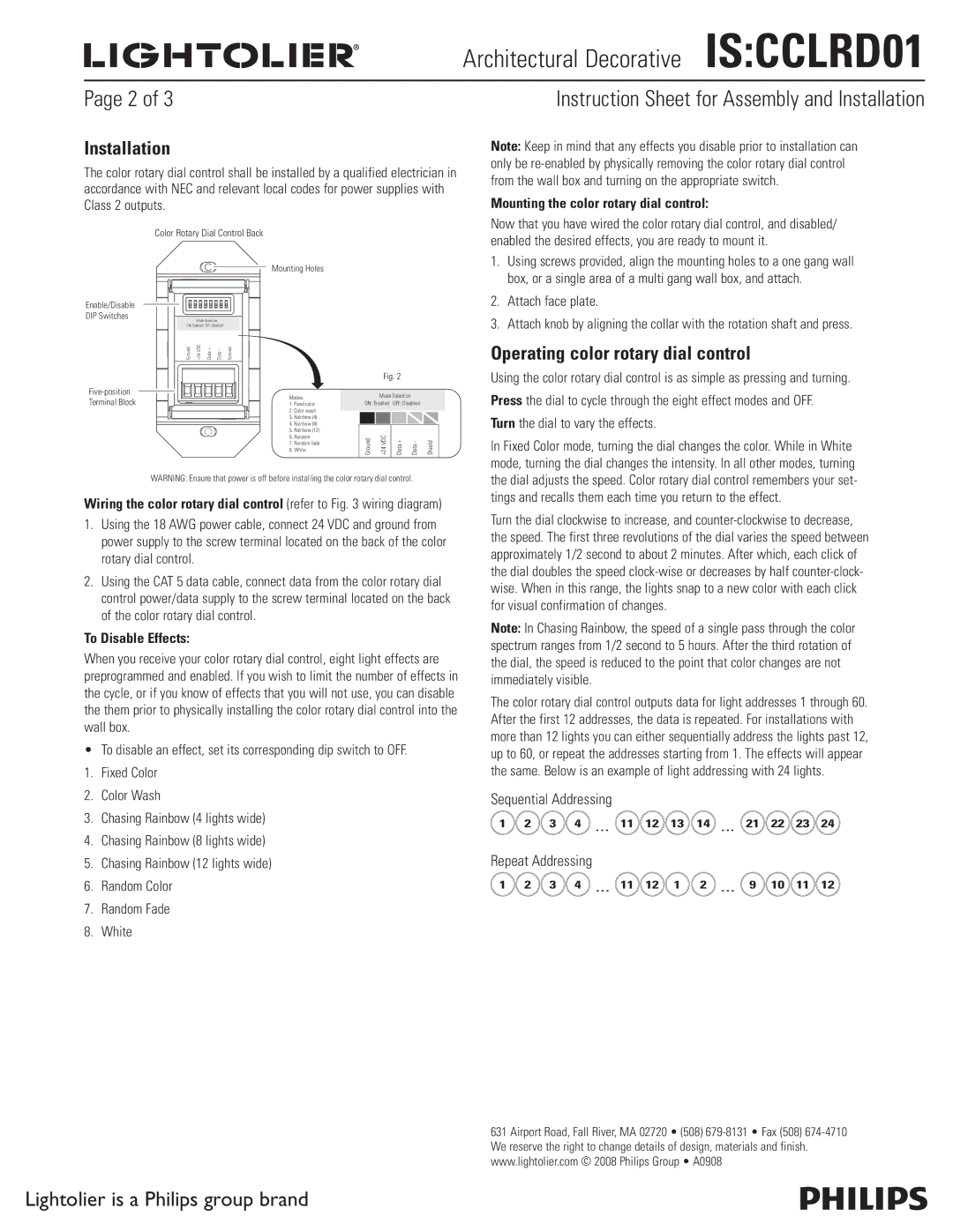
CCLRD01 specifications
Lightolier has long been a pioneer in lighting solutions, and their CCLRD01 model exemplifies modern innovation in the field. The CCLRD01 is a robust, versatile LED downlight that seamlessly blends performance, efficiency, and stylish design. This product is tailored for both commercial and residential spaces, providing an exceptional lighting experience.One of the standout features of the CCLRD01 is its energy efficiency. Utilizing high-quality LED technology, it consumes significantly less power compared to traditional incandescent or halogen lights. This not only reduces electricity bills but also minimizes the environmental impact, making it an eco-friendly choice for consumers who prioritize sustainability.
The CCLRD01 is designed with flexibility in mind. It boasts a variety of beam angles, allowing users to choose the perfect spread of light for their specific application. Whether illuminating a kitchen, highlighting artwork in a gallery, or setting a mood in a living area, this downlight can be customized to meet different lighting needs. Additionally, the adjustable color temperature ranges from warm to cool, providing an array of ambiance options suitable for any occasion.
Another impressive characteristic of the CCLRD01 is its exceptional lifespan. With an average life expectancy of over 50,000 hours, this downlight significantly reduces the frequency of replacements, making it a cost-effective investment. The durable construction ensures that the CCLRD01 can withstand the rigors of daily use without compromising on performance.
Installation is straightforward, thanks to its compact design and compatibility with most standard housing systems. The CCLRD01 features a simple, tool-free method for mounting, making it accessible for both professionals and DIY enthusiasts alike. Moreover, its sleek and minimalist aesthetic ensures that it integrates seamlessly with various interior designs, enhancing the overall decor rather than detracting from it.
Technologically, the CCLRD01 is compatible with many smart lighting systems. With dimming capabilities and integration with smart home devices, users can control their lighting remotely or set specific schedules to fit their lifestyle. The ability to link it with mobile applications allows for an unprecedented level of convenience and personalization.
In summary, the Lightolier CCLRD01 combines energy efficiency, flexibility, and advanced technology in a stylish package, making it a standout choice for consumers seeking innovative lighting solutions. Its blend of performance, durability, and aesthetic appeal positions it as a leader in the realm of modern lighting products.

