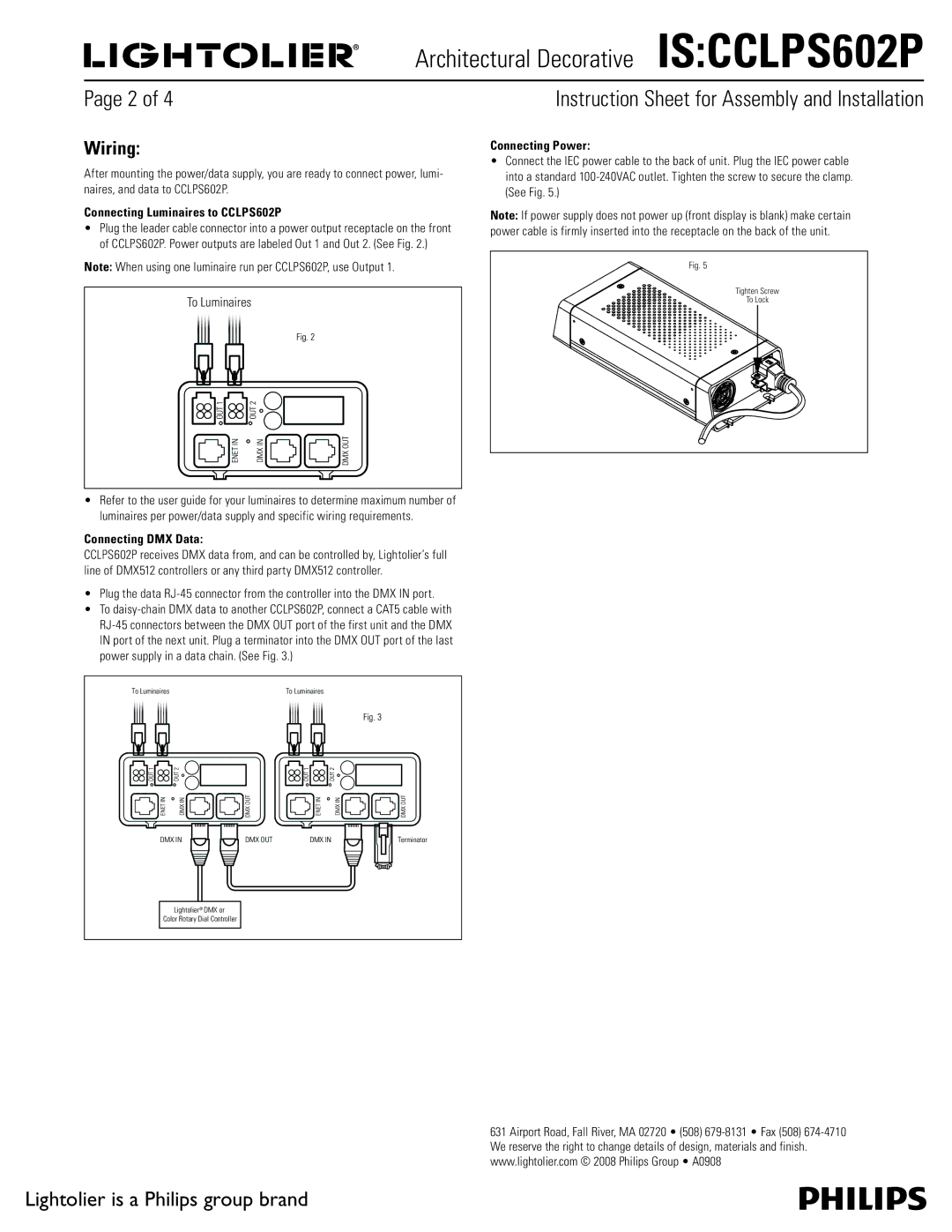
IS:CCLPS602P specifications
The Lightolier IS:CCLPS602P is a highly versatile and innovative lighting solution designed for various commercial and residential applications. This state-of-the-art fixture incorporates the latest advancements in lighting technology and delivers exceptional performance, energy efficiency, and user convenience.One of the standout features of the IS:CCLPS602P is its integrated LED technology. LEDs are renowned for their longevity and efficiency, significantly reducing the need for frequent replacements while consuming less energy compared to traditional lighting solutions. The IS:CCLPS602P provides a substantial reduction in energy costs, making it an eco-friendly choice that aligns with contemporary sustainability practices.
Another key characteristic of this model is its superior light quality. The fixture delivers a high Color Rendering Index (CRI), ensuring that colors appear more vibrant and true to life. This is particularly important in commercial settings such as retail environments where product presentation can greatly influence purchasing decisions. The adjustable color temperature options also allow users to customize the ambiance, making it suitable for various settings and occasions.
The IS:CCLPS602P is designed with ease of installation in mind. Its lightweight construction and thoughtful design allow for seamless integration into various ceiling systems, whether it be new constructions or retrofits. The fixture is compatible with various dimming systems, offering additional flexibility for controlling light levels according to user preference or time of day.
Moreover, the fixture's robust build quality ensures durability and longevity, making it ideal for high-traffic areas. Its sleek, modern design complements any decor, providing not just functional lighting but also enhancing the aesthetic appeal of the environment.
The IS:CCLPS602P also features advanced thermal management technology, which helps to dissipate heat effectively, promoting optimal performance and extending the lifespan of the LEDs. This is particularly crucial in maintaining consistent light output over time.
In summary, the Lightolier IS:CCLPS602P is a cutting-edge lighting solution that combines efficiency, style, and advanced technology. With its versatile applications, superior light quality, easy installation, and long-lasting performance, it stands out as a premier choice for those seeking reliable and aesthetically pleasing lighting solutions for both commercial and residential use.

