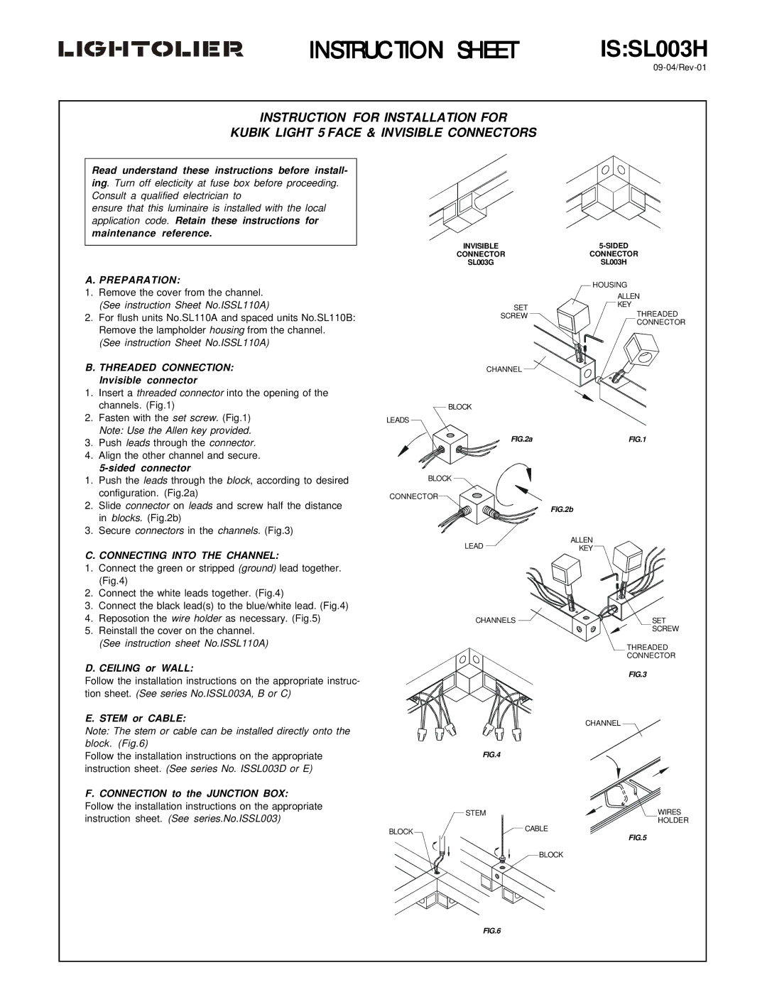
IS:SL003H specifications
The Lightolier IS:SL003H is an innovative lighting solution engineered to meet the diverse demands of modern spaces. This fixture stands out in the market due to its versatile design, advanced technologies, and focus on energy efficiency. Built with both functionality and aesthetics in mind, the IS:SL003H is perfect for residential, commercial, and hospitality environments.At the heart of the IS:SL003H is its unique LED technology, which offers significant advantages over traditional lighting solutions. The LED components provide high luminous efficacy, producing a bright and uniform light while consuming less power. This ensures lower energy bills and a reduced carbon footprint, making it an environmentally friendly choice. The fixture is designed for longevity, with an impressive lifespan that minimizes the need for frequent replacements, further contributing to sustainability efforts.
The IS:SL003H features an adjustable beam angle, allowing users to customize the distribution of light within a space. This flexibility makes it suitable for various applications, from illuminating artwork in galleries to providing general lighting in offices. The fixture's dimmable capabilities further enhance its versatility, enabling users to create the perfect ambiance tailored to the moment, be it a cozy evening gathering or a productive work environment.
Aesthetically, the IS:SL003H boasts a sleek and modern design that complements any interior decor. Available in multiple finishes, it can seamlessly blend into different settings or serve as a striking design element. The fixture's minimalist profile and clean lines ensure it remains unobtrusive while adding a touch of sophistication.
Moreover, the IS:SL003H is engineered for easy installation and maintenance. It is compatible with various mounting types, providing installers with the flexibility to adapt it to different ceiling configurations. This ease of use saves time and labor costs, making it a practical choice for contractors and architects alike.
In summary, the Lightolier IS:SL003H is an exemplary lighting fixture that combines advanced LED technology, energy efficiency, aesthetic appeal, and versatility. Its adjustable beam angle and dimming capabilities cater to diverse lighting needs, whether enhancing the mood of a space or highlighting specific features. With its sustainable design and simple installation process, the IS:SL003H is a smart choice for those seeking a reliable and stylish lighting solution.