L1PH Series Uninterruptible Power Supplies L1PH
Page 1 of 2 | 14.0 kVA Single Phase UPS System |
Operates incandescent, magnetic and electronic ballast fluorescent, high power factor compact fluorescent, and high intensity discharge (HID) lamp types.
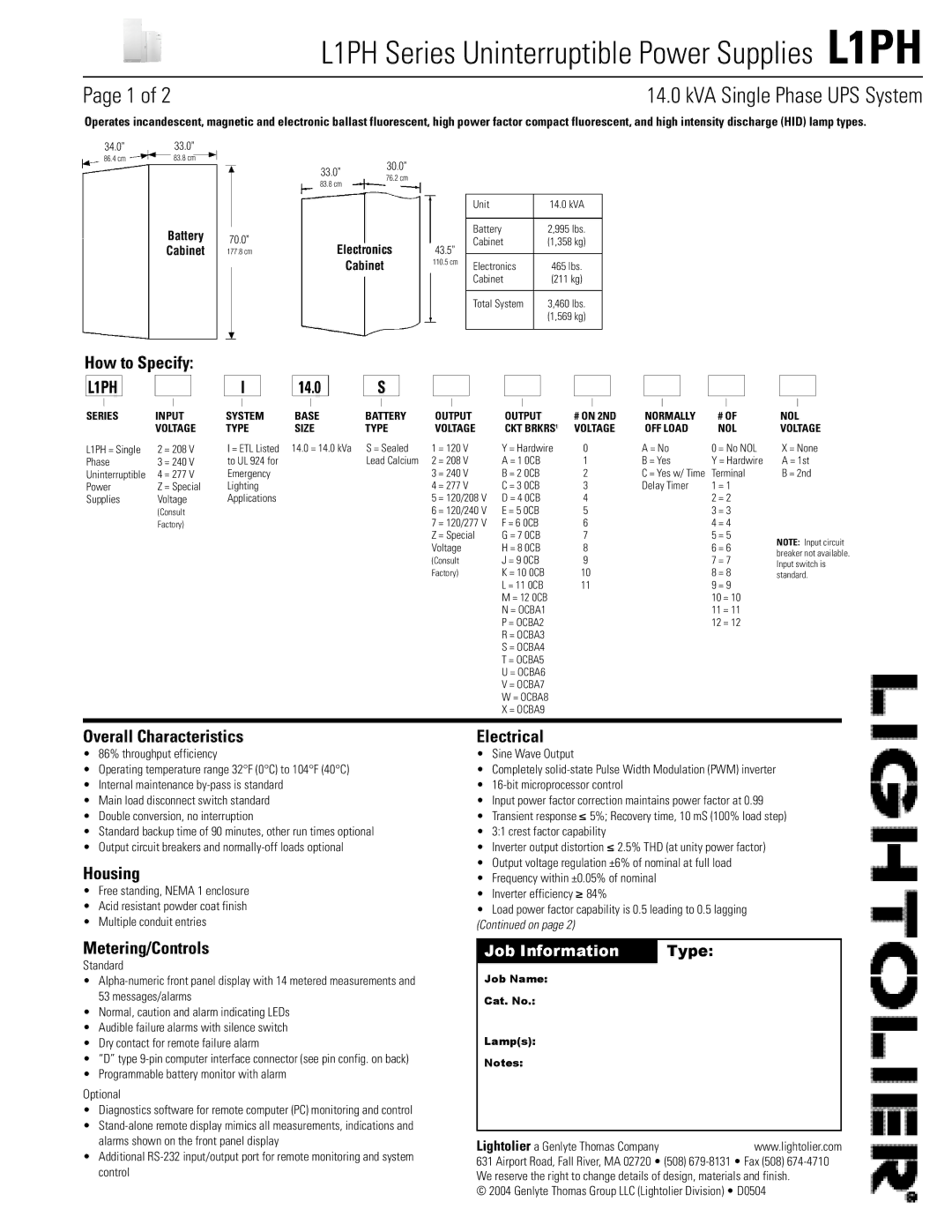
34.0” | 33.0” |
|
|
|
|
|
|
|
|
|
86.4 cm | 83.8 cm |
|
|
| 30.0” |
|
|
|
| |
|
|
| 33.0” |
|
|
|
| |||
|
|
| 76.2 cm |
|
|
|
| |||
|
|
| 83.8 cm |
|
|
|
| |||
|
|
|
|
|
|
|
|
| ||
|
|
|
|
|
|
|
| Unit |
| 14.0 kVA |
|
|
|
|
|
|
|
|
| ||
|
|
|
|
|
|
|
|
|
|
|
| Battery | 70.0” |
|
|
|
|
| Battery |
| 2,995 lbs. |
|
|
|
|
|
| Cabinet |
| (1,358 kg) | ||
| Cabinet |
| Electronics |
| 43.5” |
| ||||
| 177.8 cm |
|
|
|
|
| ||||
|
|
|
| |||||||
|
|
|
|
| Cabinet |
| 110.5 cm | Electronics |
| 465 lbs. |
|
|
|
|
|
|
|
| |||
|
|
|
|
|
|
|
| Cabinet |
| (211 kg) |
|
|
|
|
|
|
|
|
| ||
|
|
|
|
|
|
|
|
|
|
|
|
|
|
|
|
|
|
| Total System |
| 3,460 lbs. |
|
|
|
|
|
|
|
|
|
| (1,569 kg) |
|
|
|
|
|
|
|
|
|
|
|
How to Specify: |
|
|
|
|
|
|
|
|
|
|
|
|
|
|
|
|
|
| |||
L1PH |
|
| I | 14.0 | S |
|
|
|
|
|
|
|
|
|
|
|
| ||||
|
|
|
|
|
|
|
|
|
|
|
|
|
|
|
|
|
|
|
|
| |
SERIES | INPUT | SYSTEM | BASE | BATTERY | OUTPUT | OUTPUT | # ON 2ND | NORMALLY |
| # OF | |||||||||||
|
| VOLTAGE | TYPE | SIZE | TYPE | VOLTAGE | CKT BRKRS1 | VOLTAGE | OFF LOAD |
| NOL | ||||||||||
L1PH = Single | 2 = 208 V | I = ETL Listed | 14.0 = 14.0 kVa | S = Sealed | 1 = 120 V | Y = Hardwire | 0 |
| A = No | 0 | = No NOL | ||||||||||
Phase | 3 = 240 V | to UL 924 for |
|
| Lead Calcium | 2 = 208 V | A = 1 0CB | 1 |
| B = Yes | Y = Hardwire | ||||||||||
Uninterruptible | 4 = 277 V | Emergency |
|
|
|
| 3 | = 240 V | B = 2 0CB | 2 |
| C = Yes w/ Time | Terminal | ||||||||
Power | Z = Special | Lighting |
|
|
|
| 4 | = 277 V | C = 3 0CB | 3 |
| Delay Timer | 1 | = 1 | |||||||
Supplies | Voltage | Applications |
|
|
|
| 5 | = 120/208 V | D = 4 0CB | 4 |
|
|
| 2 | = 2 | ||||||
|
| (Consult |
|
|
|
|
|
| 6 | = 120/240 V | E = 5 0CB | 5 |
|
|
| 3 | = 3 | ||||
|
| Factory) |
|
|
|
|
|
| 7 | = 120/277 V | F = 6 0CB | 6 |
|
|
| 4 | = 4 | ||||
|
|
|
|
|
|
|
|
|
| Z = Special | G = 7 0CB | 7 |
|
|
| 5 | = 5 | ||||
|
|
|
|
|
|
|
|
|
| Voltage | H = 8 0CB | 8 |
|
|
| 6 | = 6 | ||||
|
|
|
|
|
|
|
|
|
| (Consult | J = 9 0CB | 9 |
|
|
| 7 | = 7 | ||||
|
|
|
|
|
|
|
|
|
| Factory) | K = 10 0CB | 10 |
|
|
| 8 | = 8 | ||||
|
|
|
|
|
|
|
|
|
|
|
|
| L = 11 0CB | 11 |
|
|
| 9 | = 9 | ||
|
|
|
|
|
|
|
|
|
|
|
|
| M = 12 0CB |
|
|
|
| 10 = 10 | |||
|
|
|
|
|
|
|
|
|
|
|
|
| N = OCBA1 |
|
|
|
| 11 = 11 | |||
|
|
|
|
|
|
|
|
|
|
|
|
| P = OCBA2 |
|
|
|
| 12 = 12 | |||
|
|
|
|
|
|
|
|
|
|
|
|
| R = OCBA3 |
|
|
|
|
|
|
| |
|
|
|
|
|
|
|
|
|
|
|
|
| S = OCBA4 |
|
|
|
|
|
|
| |
T = OCBA5
U = OCBA6
V = OCBA7
W = OCBA8
X = OCBA9
NOL
VOLTAGE
X = None
A = 1st
B = 2nd
NOTE: Input circuit breaker not available. Input switch is standard.
Overall Characteristics
•86% throughput efficiency
•Operating temperature range 32°F (0°C) to 104°F (40°C)
•Internal maintenance
•Main load disconnect switch standard
•Double conversion, no interruption
•Standard backup time of 90 minutes, other run times optional
•Output circuit breakers and
Housing
•Free standing, NEMA 1 enclosure
•Acid resistant powder coat finish
•Multiple conduit entries
Metering/Controls
Standard
•
•Normal, caution and alarm indicating LEDs
•Audible failure alarms with silence switch
•Dry contact for remote failure alarm
•“D” type
•Programmable battery monitor with alarm
Optional
•Diagnostics software for remote computer (PC) monitoring and control
•
•Additional
Electrical
•Sine Wave Output
•Completely
•
•Input power factor correction maintains power factor at 0.99
•Transient response ≤ 5%; Recovery time, 10 mS (100% load step)
•3:1 crest factor capability
•Inverter output distortion ≤ 2.5% THD (at unity power factor)
•Output voltage regulation ±6% of nominal at full load
•Frequency within ±0.05% of nominal
•Inverter efficiency ≥ 84%
•Load power factor capability is 0.5 leading to 0.5 lagging (Continued on page 2)
Job Name:![]() Cat. No.:
Cat. No.:
Lamp(s):![]() Notes:
Notes:
Lightolier a Genlyte Thomas Companywww.lightolier.com 631 Airport Road, Fall River, MA 02720 • (508)
© 2004 Genlyte Thomas Group LLC (Lightolier Division) • D0504