
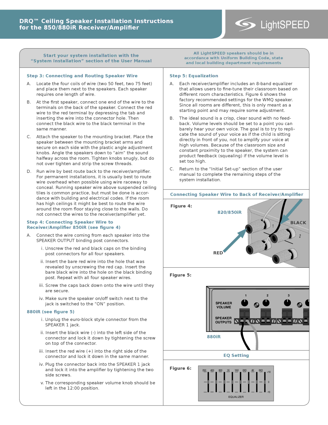
850, 880iR specifications
LightSpeed Technologies has established itself as a pioneer in the realm of wireless audio solutions, showcasing their innovative products designed for educational and professional environments. Among their standout offerings are the LightSpeed 850 and 880iR systems, which blend cutting-edge technology with user-friendly features to enhance the learning experience.The LightSpeed 850 offers impeccable sound clarity and reliability, optimizing classroom communication. This system is equipped with infrared (IR) technology, ensuring robust audio transmission without the interference often seen in RF systems. The 850 includes a lightweight, comfortable teacher microphone that provides freedom of movement around the classroom. The microphone's design is tailored for ease of use, allowing instructors to focus on teaching rather than managing audio equipment.
The LightSpeed 880iR builds upon the success of the 850 by offering advanced features aimed at enhancing engagement and collaboration in educational settings. This system includes dual-channel IR transmission for superior audio coverage and the flexibility to connect multiple microphones simultaneously. Teachers can use the 880iR with confidence, knowing that their voice will be transmitted clearly, regardless of the classroom layout or size.
Both systems feature a robust audio processing capability, allowing for crystal-clear sound delivery of speech and any multimedia content. The integrated audio mixing allows for the incorporation of additional audio sources, such as projectors or computers, ensuring that multimedia presentations are amplified without sacrificing voice clarity. An intuitive control panel simplifies system management, providing easy access to audio adjustments.
The high efficiency of IR technology employed in both models ensures that audio remains secure and private, making these systems ideal for environments where confidentiality is paramount. This technology also mitigates the risk of interference from other wireless devices, providing an uninterrupted teaching experience.
LightSpeed Technologies has carefully designed both the 850 and 880iR systems with durability in mind, ensuring that they can withstand the rigors of classroom usage. Their commitment to quality is evident in the materials and craftsmanship used to create these systems, making them a worthy investment for educational institutions looking to enhance their audio capabilities.
In summary, the LightSpeed 850 and 880iR systems represent the forefront of wireless audio technology in educational settings. With an emphasis on user-friendliness, superior sound quality, and advanced technological features, these systems stand poised to transform the way teachers and students engage in the classroom environment.