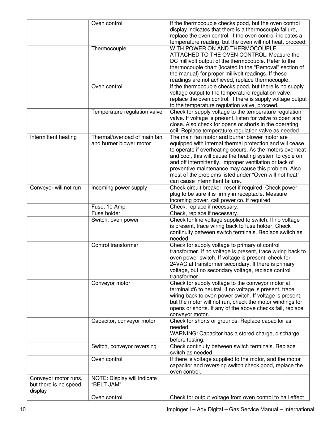
| Oven control | If the thermocouple checks good, but the oven control |
|
| display indicates that there is a thermocouple failure, |
|
| replace the oven control. If the oven control indicates a |
|
| temperature reading, but the oven will not heat, proceed. |
| Thermocouple | WITH POWER ON AND THERMOCOUPLE |
|
| ATTACHED TO THE OVEN CONTROL: Measure the |
|
| DC millivolt output of the thermocouple. Refer to the |
|
| thermocouple chart (located in the “Removal” section of |
|
| the manual) for proper millivolt readings. If these |
|
| readings are not achieved, replace thermocouple. |
| Oven control | If the thermocouple checks good, but there is no supply |
|
| voltage output to the temperature regulation valve, |
|
| replace the oven control. If there is supply voltage output |
|
| to the temperature regulation valve, proceed. |
| Temperature regulation valve | Check for supply voltage to the temperature regulation |
|
| valve. If voltage is present, listen for valve to open and |
|
| close. Also check for opens or shorts in the operating |
|
| coil. Replace temperature regulation valve as needed. |
Intermittent heating | Thermal/overload of main fan | The main fan motor and burner blower motor are |
| and burner blower motor | equipped with internal thermal protection and will cease |
|
| to operate if overheating occurs. As the motors overheat |
|
| and cool, this will cause the heating system to cycle on |
|
| and off intermittently. Improper ventilation or lack of |
|
| preventive maintenance may cause this problem. Also |
|
| most of the problems listed under “Oven will not heat” |
|
| can cause intermittent failure. |
Conveyor will not run | Incoming power supply | Check circuit breaker, reset if required. Check power |
|
| plug to be sure it is firmly in receptacle. Measure |
|
| incoming power, call power co. if required. |
| Fuse, 10 Amp | Check, replace if necessary. |
| Fuse holder | Check, replace if necessary. |
| Switch, oven power | Check for line voltage supplied to switch. If no voltage |
|
| is present, trace wiring back to fuse holder. Check |
|
| continuity between switch terminals. Replace switch as |
|
| needed. |
| Control transformer | Check for supply voltage to primary of control |
|
| transformer. If no voltage is present, trace wiring back to |
|
| oven power switch. If voltage is present, check for |
|
| 24VAC at transformer secondary. If there is primary |
|
| voltage, but no secondary voltage, replace control |
|
| transformer. |
| Conveyor motor | Check for supply voltage to the conveyor motor at |
|
| terminal #6 to neutral. If no voltage is present, trace |
|
| wiring back to oven power switch. If voltage is present, |
|
| but the motor will not run, check the motor windings for |
|
| opens or shorts. If any of the above checks fail, replace |
|
| conveyor motor. |
| Capacitor, conveyor motor | Check for shorts or grounds. Replace capacitor as |
|
| needed. |
|
| WARNING: Capacitor has a stored charge, discharge |
|
| before testing. |
| Switch, conveyor reversing | Check continuity between switch terminals. Replace |
|
| switch as needed. |
| Oven control | If there is voltage supplied to the motor, and the motor |
|
| capacitor and reversing switch check good, replace the |
|
| oven control. |
Conveyor motor runs, | NOTE: Display will indicate |
|
but there is no speed | “BELT JAM” |
|
display |
|
|
| Oven control | Check for output voltage from oven control to hall effect |
10 | Impinger I – Adv Digital – Gas Service Manual – International |
