|
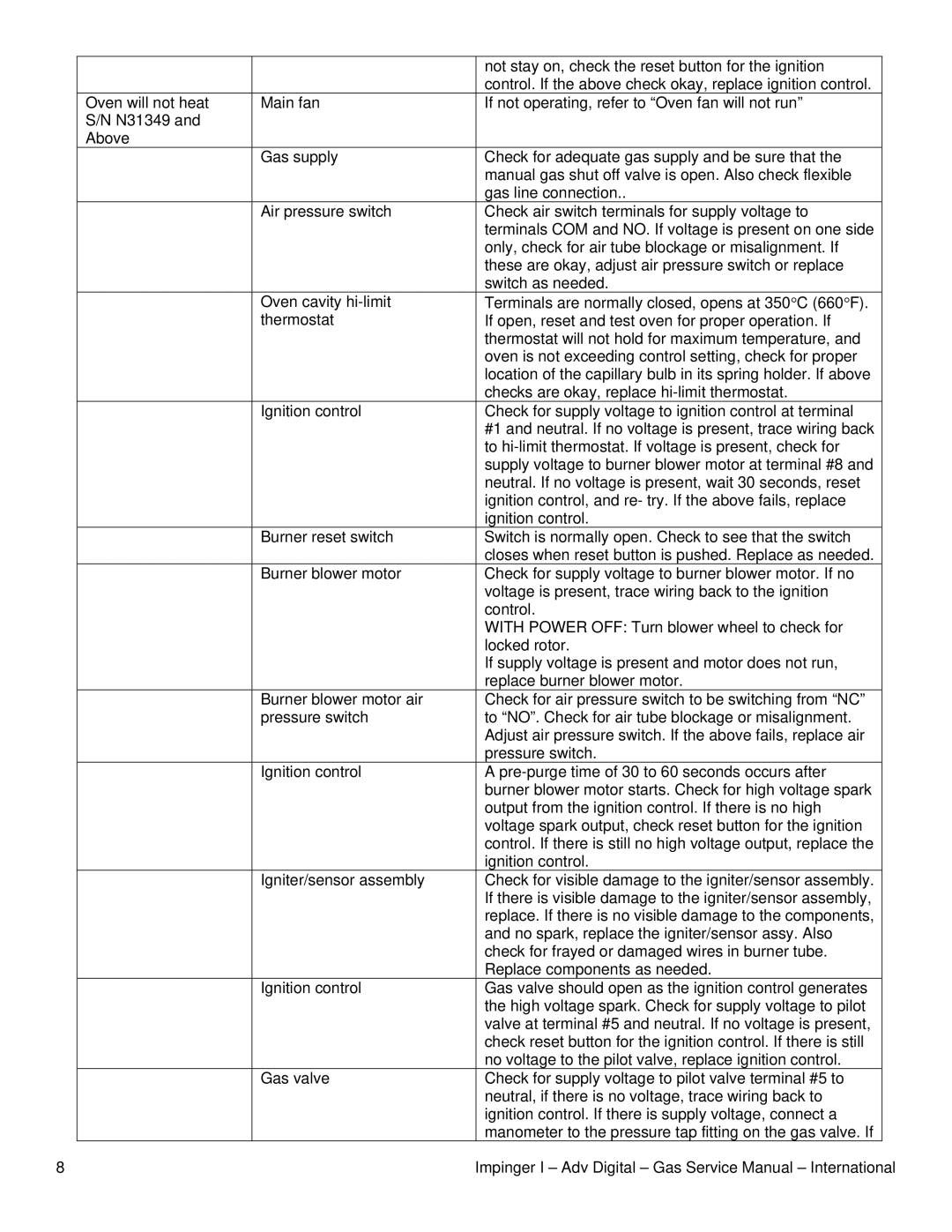
| not stay on, check the reset button for the ignition |
|
| control. If the above check okay, replace ignition control. |
Oven will not heat | Main fan | If not operating, refer to “Oven fan will not run” |
S/N N31349 and |
|
|
Above |
|
|
| Gas supply | Check for adequate gas supply and be sure that the |
|
| manual gas shut off valve is open. Also check flexible |
|
| gas line connection.. |
| Air pressure switch | Check air switch terminals for supply voltage to |
|
| terminals COM and NO. If voltage is present on one side |
|
| only, check for air tube blockage or misalignment. If |
|
| these are okay, adjust air pressure switch or replace |
|
| switch as needed. |
| Oven cavity | Terminals are normally closed, opens at 350°C (660°F). |
| thermostat | If open, reset and test oven for proper operation. If |
|
| thermostat will not hold for maximum temperature, and |
|
| oven is not exceeding control setting, check for proper |
|
| location of the capillary bulb in its spring holder. If above |
|
| checks are okay, replace |
| Ignition control | Check for supply voltage to ignition control at terminal |
|
| #1 and neutral. If no voltage is present, trace wiring back |
|
| to |
|
| supply voltage to burner blower motor at terminal #8 and |
|
| neutral. If no voltage is present, wait 30 seconds, reset |
|
| ignition control, and re- try. If the above fails, replace |
|
| ignition control. |
| Burner reset switch | Switch is normally open. Check to see that the switch |
|
| closes when reset button is pushed. Replace as needed. |
| Burner blower motor | Check for supply voltage to burner blower motor. If no |
|
| voltage is present, trace wiring back to the ignition |
|
| control. |
|
| WITH POWER OFF: Turn blower wheel to check for |
|
| locked rotor. |
|
| If supply voltage is present and motor does not run, |
|
| replace burner blower motor. |
| Burner blower motor air | Check for air pressure switch to be switching from “NC” |
| pressure switch | to “NO”. Check for air tube blockage or misalignment. |
|
| Adjust air pressure switch. If the above fails, replace air |
|
| pressure switch. |
| Ignition control | A |
|
| burner blower motor starts. Check for high voltage spark |
|
| output from the ignition control. If there is no high |
|
| voltage spark output, check reset button for the ignition |
|
| control. If there is still no high voltage output, replace the |
|
| ignition control. |
| Igniter/sensor assembly | Check for visible damage to the igniter/sensor assembly. |
|
| If there is visible damage to the igniter/sensor assembly, |
|
| replace. If there is no visible damage to the components, |
|
| and no spark, replace the igniter/sensor assy. Also |
|
| check for frayed or damaged wires in burner tube. |
|
| Replace components as needed. |
| Ignition control | Gas valve should open as the ignition control generates |
|
| the high voltage spark. Check for supply voltage to pilot |
|
| valve at terminal #5 and neutral. If no voltage is present, |
|
| check reset button for the ignition control. If there is still |
|
| no voltage to the pilot valve, replace ignition control. |
| Gas valve | Check for supply voltage to pilot valve terminal #5 to |
|
| neutral, if there is no voltage, trace wiring back to |
|
| ignition control. If there is supply voltage, connect a |
|
| manometer to the pressure tap fitting on the gas valve. If |
8 | Impinger I – Adv Digital – Gas Service Manual – International |
