INSTALLATION |
3.Remove the head mounting block from the
Note: Before mounting an
1.Remove the four screws mounting the gearbox assembly to the motor adapter plate, and remove gearbox.
The drive motor is to be in the vertical position and the drive rolls are to face the front. Loosen the head face plate clamp screw and rotate the face plate so that the idle roll arm is down. Install the nozzle, wire straight- ener and flux hopper (if used) per the
When using the K225 Twinarc nozzle, a K219 flux hopper and a standard head mounting on a travel car- riage, and when welding from left to right, a special 12" flux tube is required. The tube, which is included with the Spreadarc, may be trimmed to length to fit the installation. In addition, it is necessary to
2.Remove the three screws mounting the adapter plate to the motor, rotate the adapter plate 90° clockwise and replace the three mounting screws.
3.Remount the gearbox assembly with the four mounting screws.
HIGH FREQUENCY PROTECTION
Locate the Spreadarc away from radio controlled machinery. The normal operation of the Spreadarc may adversely affect the operation of RF controlled equipment, which may result in bodily injury or dam- age to the equipment.
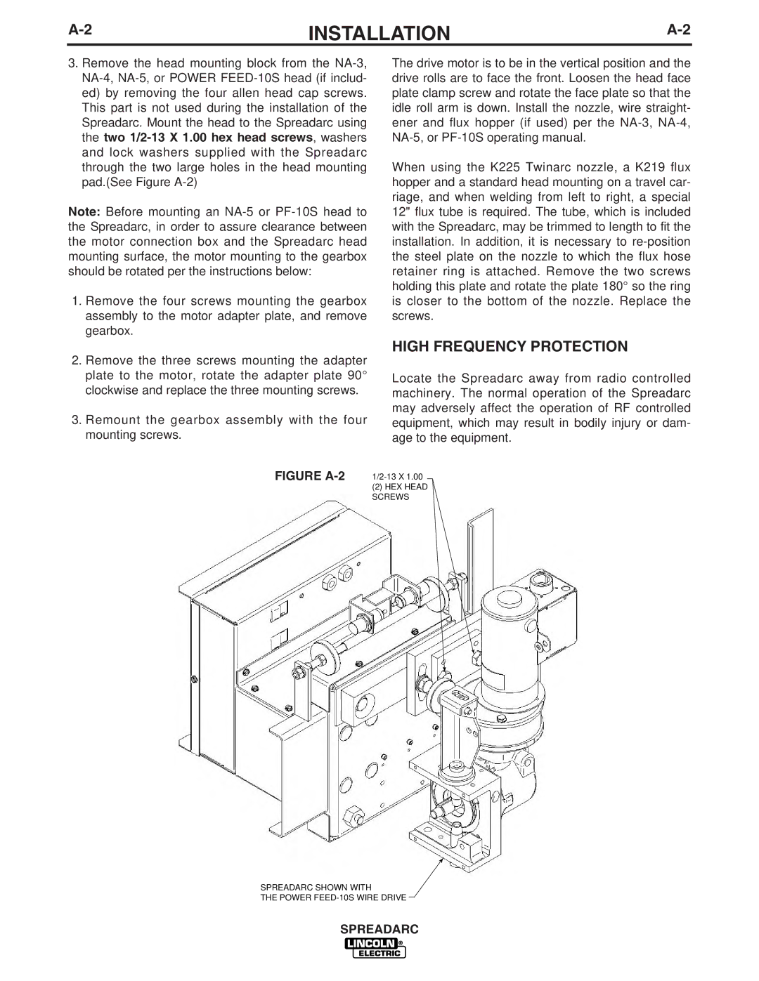
FIGURE A-2
(2)HEX HEAD SCREWS
SPREADARC SHOWN WITH
THE POWER
SPREADARC