OPERATION | ||
|
|
|
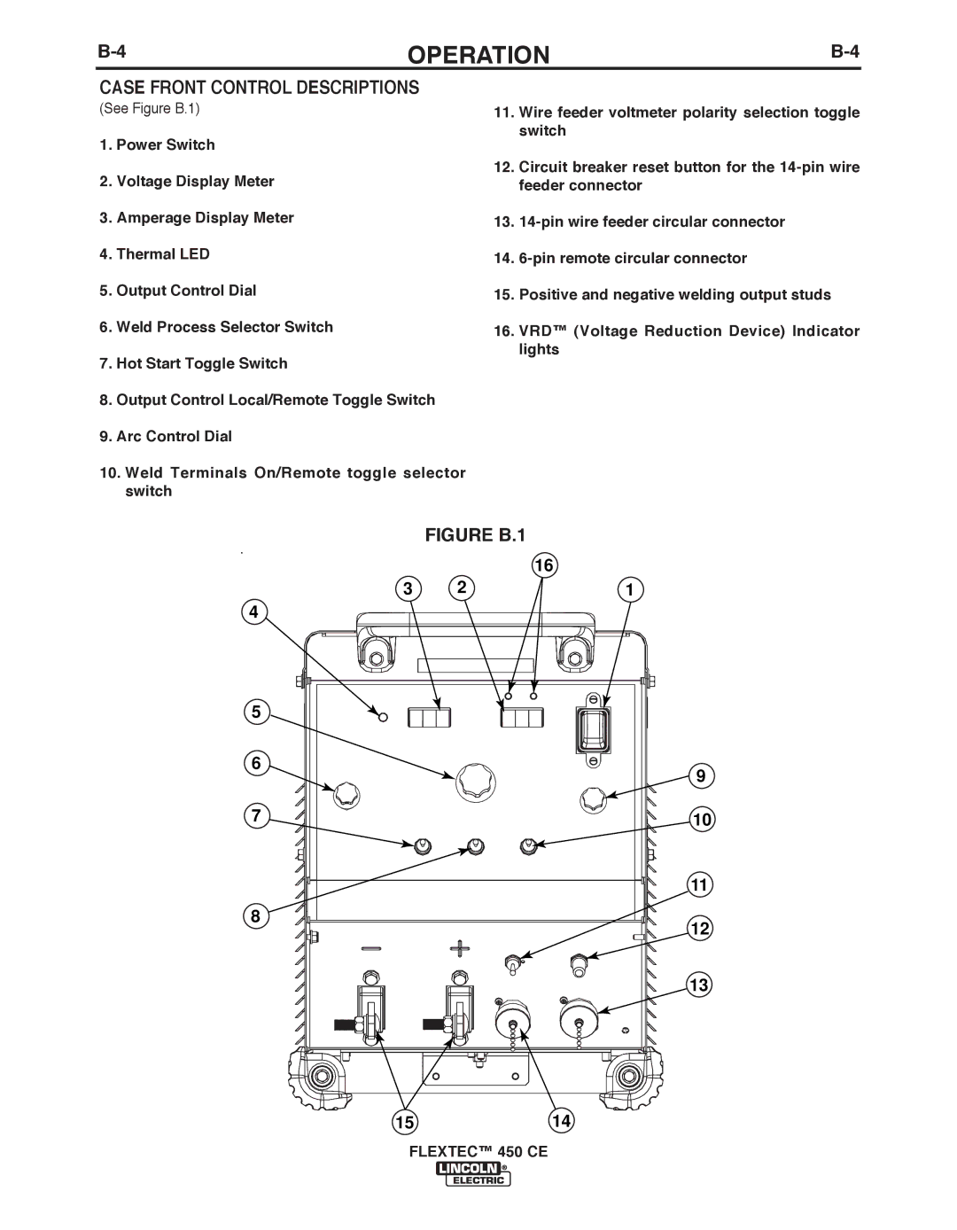
CASE FRONT CONTROL DESCRIPTIONS
(See Figure B.1)
1.Power Switch
2.Voltage Display Meter
3.Amperage Display Meter
4.Thermal LED
5.Output Control Dial
6.Weld Process Selector Switch
7.Hot Start Toggle Switch
8.Output Control Local/Remote Toggle Switch
9.Arc Control Dial
10.Weld Terminals On/Remote toggle selector switch
11.Wire feeder voltmeter polarity selection toggle switch
12.Circuit breaker reset button for the
13.
14.
15.Positive and negative welding output studs
16.VRD™ (Voltage Reduction Device) Indicator lights
FIGURE b.1
|
| 16 |
3 | 2 | 1 |
4
5
6
9
7 | 10 |
11
8
12
13
1514