INSTALLATION | ||
|
|
|
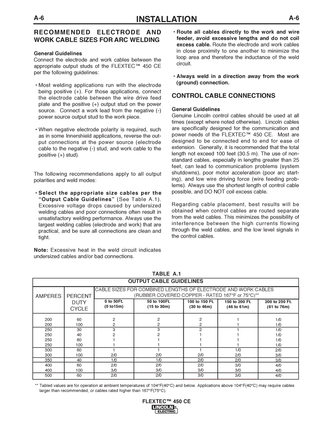
RECOMMENDED ELECTRODE AND WORK CAbLE SIzES FOR ARC WELDING
General Guidelines
Connect the electrode and work cables between the appropriate output studs of the FLEXTEC™ 450 CE per the following guidelines:
•Most welding applications run with the electrode being positive (+). For those applications, connect the electrode cable between the wire drive feed plate and the positive (+) output stud on the power source. Connect a work lead from the negative
•When negative electrode polarity is required, such as in some Innershield applications, reverse the out- put connections at the power source (electrode cable to the negative
The following recommendations apply to all output polarities and weld modes:
•Select the appropriate size cables per the “Output Cable Guidelines” (See Table A.1). Excessive voltage drops caused by undersized welding cables and poor connections often result in unsatisfactory welding performance. Always use the largest welding cables (electrode and work) that are practical, and be sure all connections are clean and tight.
Note: Excessive heat in the weld circuit indicates undersized cables and/or bad connections.
•Route all cables directly to the work and wire feeder, avoid excessive lengths and do not coil excess cable. Route the electrode and work cables in close proximity to one another to minimize the loop area and therefore the inductance of the weld circuit.
•Always weld in a direction away from the work (ground) connection.
CONTROL CAbLE CONNECTIONS
General Guidelines
Genuine Lincoln control cables should be used at all times (except where noted otherwise). Lincoln cables are specifically designed for the communication and power needs of the FLEXTEC™ 450 CE. Most are designed to be connected end to end for ease of extension. Generally, it is recommended that the total length not exceed 100 feet (30.5 m). The use of non- standard cables, especially in lengths greater than 25 feet, can lead to communication problems (system shutdowns), poor motor acceleration (poor arc start- ing), and low wire driving force (wire feeding prob- lems). Always use the shortest length of control cable possible, and DO NOT coil excess cable.
Regarding cable placement, best results will be obtained when control cables are routed separate from the weld cables. This minimizes the possibility of interference between the high currents flowing through the weld cables, and the low level signals in the control cables.
TAbLE A.1
OUTPUT CAbLE GUIDELINES
|
| CABLE SIZES FOR COMBINED LENGTHS OF ELECTRODE AND WORK CABLES | |||||
AMPERES | PERCENT |
| (RUBBER COVERED COPPER - RATED 167°F or 75°C)** |
| |||
| DUTY | 0 to 50Ft. | 50 to 100Ft. | 100 to 150 Ft. | 150 to 200 Ft. |
| 200 to 250 Ft. |
| |||||||
| CYCLE | (0 to15m) | (15 to 30m) | (30 to 46m) | (46 to 61m) |
| (61 to 76m) |
|
|
|
|
|
|
| |
|
|
|
|
|
|
|
|
200 | 60 | 2 | 2 | 2 | 1 |
| 1/0 |
200 | 100 | 2 | 2 | 2 | 1 |
| 1/0 |
250 | 30 | 3 | 3 | 2 | 1 |
| 1/0 |
250 | 40 | 2 | 2 | 1 | 1 |
| 1/0 |
250 | 60 | 1 | 1 | 1 | 1 |
| 1/0 |
250 | 100 | 1 | 1 | 1 | 1 |
| 1/0 |
300 | 60 | 1 | 1 | 1 | 1/0 |
| 2/0 |
300 | 100 | 2/0 | 2/0 | 2/0 | 2/0 |
| 3/0 |
350 | 40 | 1/0 | 1/0 | 2/0 | 2/0 |
| 3/0 |
400 | 60 | 2/0 | 2/0 | 2/0 | 3/0 |
| 4/0 |
400 | 100 | 3/0 | 3/0 | 3/0 | 3/0 |
| 4/0 |
500 | 60 | 2/0 | 2/0 | 3/0 | 3/0 |
| 4/0 |
|
|
|
|
|
|
|
|
**Tabled values are for operation at ambient temperatures of 104°F(40°C) and below. Applications above 104°F(40°C) may require cables larger than recommended, or cables rated higher than 167°F(75°C).