B-6

OPERATION

B-6


POWER SOURCE OPERATION

WARNING

ELECTRIC SHOCK can kill.

Have an electrician install and service this equipment.

Turn the input power off at the fuse box before working on equipment.

Do not touch electrically hot parts.

---------------------------------------------------------------------

Duty Cycle and Time Period

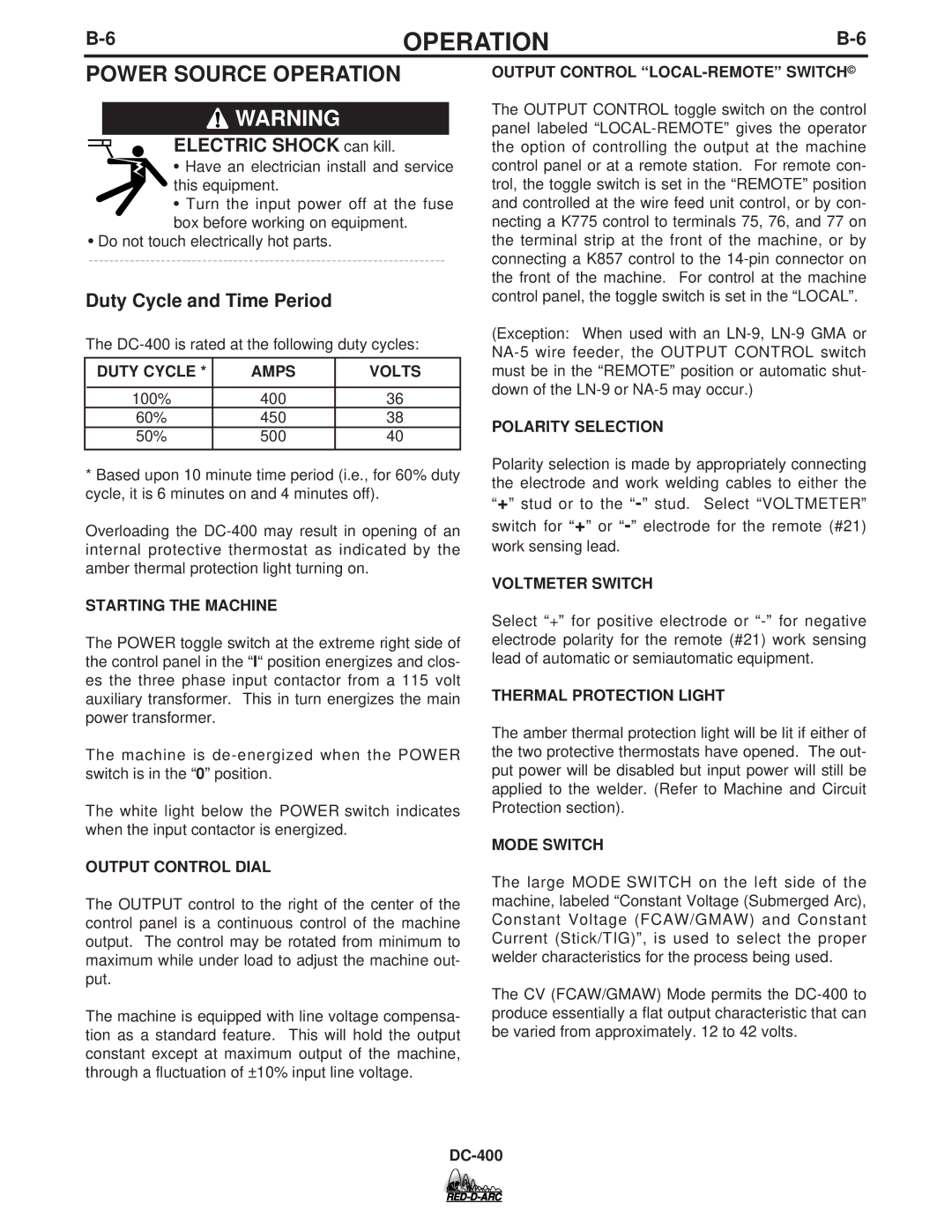
The DC-400 is rated at the following duty cycles:

DUTY CYCLE *

AMPS

VOLTS


100%

400

36

60%

450

38

50%

500

40


*Based upon 10 minute time period (i.e., for 60% duty cycle, it is 6 minutes on and 4 minutes off).

Overloading the DC-400 may result in opening of an internal protective thermostat as indicated by the amber thermal protection light turning on.

STARTING THE MACHINE

The POWER toggle switch at the extreme right side of the control panel in the “I“ position energizes and clos- es the three phase input contactor from a 115 volt auxiliary transformer. This in turn energizes the main power transformer.

The machine is de-energized when the POWER switch is in the “0” position.

The white light below the POWER switch indicates when the input contactor is energized.

OUTPUT CONTROL DIAL

The OUTPUT control to the right of the center of the control panel is a continuous control of the machine output. The control may be rotated from minimum to maximum while under load to adjust the machine out- put.

The machine is equipped with line voltage compensa- tion as a standard feature. This will hold the output constant except at maximum output of the machine, through a fluctuation of ±10% input line voltage.

OUTPUT CONTROL “LOCAL-REMOTE” SWITCH©

The OUTPUT CONTROL toggle switch on the control panel labeled “LOCAL-REMOTE” gives the operator the option of controlling the output at the machine control panel or at a remote station. For remote con- trol, the toggle switch is set in the “REMOTE” position and controlled at the wire feed unit control, or by con- necting a K775 control to terminals 75, 76, and 77 on the terminal strip at the front of the machine, or by connecting a K857 control to the 14-pin connector on the front of the machine. For control at the machine control panel, the toggle switch is set in the “LOCAL”.

(Exception: When used with an LN-9, LN-9 GMA or NA-5 wire feeder, the OUTPUT CONTROL switch must be in the “REMOTE” position or automatic shut- down of the LN-9 or NA-5 may occur.)

POLARITY SELECTION

Polarity selection is made by appropriately connecting the electrode and work welding cables to either the “+” stud or to the - stud. Select “VOLTMETER” switch for “+” or - electrode for the remote (#21) work sensing lead.

VOLTMETER SWITCH

Select “+” for positive electrode or “-” for negative electrode polarity for the remote (#21) work sensing lead of automatic or semiautomatic equipment.

THERMAL PROTECTION LIGHT

The amber thermal protection light will be lit if either of the two protective thermostats have opened. The out- put power will be disabled but input power will still be applied to the welder. (Refer to Machine and Circuit Protection section).

MODE SWITCH

The large MODE SWITCH on the left side of the machine, labeled “Constant Voltage (Submerged Arc), Constant Voltage (FCAW/GMAW) and Constant Current (Stick/TIG)”, is used to select the proper welder characteristics for the process being used.

The CV (FCAW/GMAW) Mode permits the DC-400 to produce essentially a flat output characteristic that can be varied from approximately. 12 to 42 volts.

DC-400

Page 22
Image 22
Lincoln Electric DC-400 Power Source Operation, Duty Cycle and Time Period, Duty Cycle Amps Volts, Starting the Machine

DC-400 specifications

The Lincoln Electric DC-400 is a versatile and robust DC arc welding power source designed to meet the demands of various industrial applications. Known for its reliability and performance, the DC-400 is ideal for both professional welders and fabrication shops requiring robust equipment that can handle challenging welding tasks.

One of the main features of the DC-400 is its ability to provide a smooth, stable arc, which is essential for achieving high-quality welds. This welding machine is capable of delivering a wide amperage range, typically from 20 to 400 amperes, making it suitable for various welding processes, including MIG, TIG, and Stick welding. The unit's high output capabilities allow it to effectively weld a variety of materials, such as steel, stainless steel, and various alloys.

In terms of technology, the DC-400 integrates advanced power conversion technology that enhances energy efficiency while minimizing heat loss during operation. This not only contributes to lower operating costs but also ensures a longer service life for the machine. The DC-400 features a durable, rugged design, with a robust steel frame that can withstand the rigors of heavy industrial use while providing an IP23 rating for protection against moisture and dust.

Another notable characteristic of the DC-400 is its ease of use. The intuitive controls allow for quick adjustments to settings, enabling welders to easily adapt to different job requirements. The arc characteristics of the DC-400 can be fine-tuned to optimize performance for different welding applications, ensuring consistent results every time.

Moreover, the DC-400 is equipped with built-in safety features such as thermal overload protection, which prevents damage to the machine in case of prolonged operation under heavy loads. This feature enhances the safety of the operator and extends the life of the welding machine.

Overall, the Lincoln Electric DC-400 stands out as a reliable and efficient welding power source. Its combination of high-performance capabilities, advanced technology, and next-level usability makes it a popular choice in the industry. Whether for heavy fabrication, maintenance, or repair work, the DC-400 continues to prove itself as an indispensable tool for professional welders seeking quality and durability in their equipment.