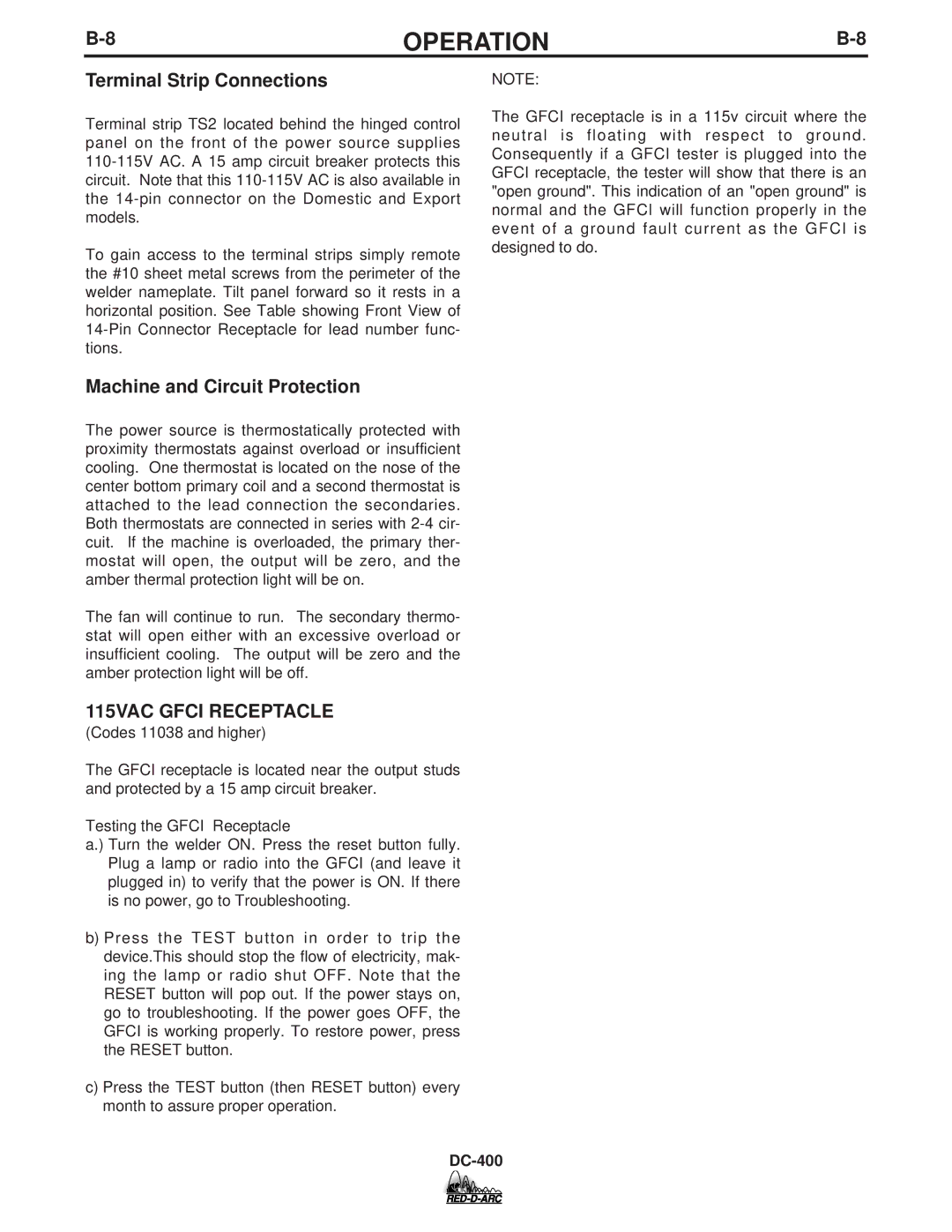
DC-400 specifications
The Lincoln Electric DC-400 is a versatile and robust DC arc welding power source designed to meet the demands of various industrial applications. Known for its reliability and performance, the DC-400 is ideal for both professional welders and fabrication shops requiring robust equipment that can handle challenging welding tasks.One of the main features of the DC-400 is its ability to provide a smooth, stable arc, which is essential for achieving high-quality welds. This welding machine is capable of delivering a wide amperage range, typically from 20 to 400 amperes, making it suitable for various welding processes, including MIG, TIG, and Stick welding. The unit's high output capabilities allow it to effectively weld a variety of materials, such as steel, stainless steel, and various alloys.
In terms of technology, the DC-400 integrates advanced power conversion technology that enhances energy efficiency while minimizing heat loss during operation. This not only contributes to lower operating costs but also ensures a longer service life for the machine. The DC-400 features a durable, rugged design, with a robust steel frame that can withstand the rigors of heavy industrial use while providing an IP23 rating for protection against moisture and dust.
Another notable characteristic of the DC-400 is its ease of use. The intuitive controls allow for quick adjustments to settings, enabling welders to easily adapt to different job requirements. The arc characteristics of the DC-400 can be fine-tuned to optimize performance for different welding applications, ensuring consistent results every time.
Moreover, the DC-400 is equipped with built-in safety features such as thermal overload protection, which prevents damage to the machine in case of prolonged operation under heavy loads. This feature enhances the safety of the operator and extends the life of the welding machine.
Overall, the Lincoln Electric DC-400 stands out as a reliable and efficient welding power source. Its combination of high-performance capabilities, advanced technology, and next-level usability makes it a popular choice in the industry. Whether for heavy fabrication, maintenance, or repair work, the DC-400 continues to prove itself as an indispensable tool for professional welders seeking quality and durability in their equipment.
