F-2

DIAGRAMS

F-2


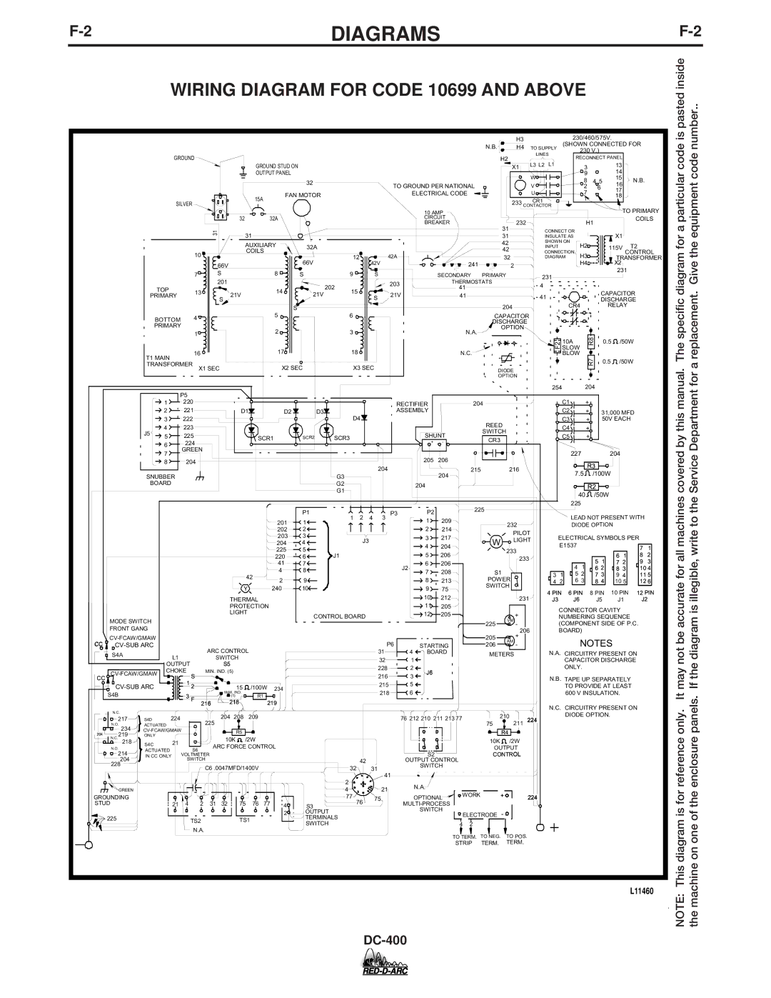
WIRING DIAGRAM FOR CODE 10699 AND ABOVE

pasted inside

number..

GROUND

A

SILVER


A


31


10


66V


7

S


201

TOP

13


PRIMARY

S


BOTTOM

4


PRIMARY


1


16


T1 MAIN

TRANSFORMER X1 SEC


GROUND STUD ON


OUTPUT PANEL


32


15A

FAN MOTOR


32

32A


31


AUXILIARY

32A


COILS


A


66V


8

S


A


14

202

21V

21V


S

5

2

17

X2 SEC

12

42V


9

S

15

A

S


6

3

18

X3 SEC


H3


230/460/575V.


N.B.

H4 TO SUPPLY

(SHOWN CONNECTED FOR

230 V.)


LINES


H2


RECONNECT PANEL


L3 L2

L1


X1

3


13


W


9


14


8

4 5

15

N.B.

TO GROUND PER NATIONAL


V


16


2

6


ELECTRICAL CODE


U


A7


17


18


CR1


1


233 CONTACTOR


TO PRIMARY

10 AMP


CIRCUIT

232


H1


COILS

BREAKER


31CONNECT OR


31

INSULATE AS


X1


42

SHOWN ON

H2


T2


42

INPUT

115V


CONNECTION


42A


32

H3


CONTROL

A

DIAGRAM


TRANSFORMER


241

2


H4


X2


SECONDARY

PRIMARY

231


231


203

THERMOSTATS

4


41


21V


CAPACITOR

41


41


DISCHARGE


204

CR4

RELAY


CAPACITOR


DISCHARGE


N.A.

OPTION


R8


10A

0.5

/50W


N.C.


F2SLOW


BLOW

R7


DIODE


0.5

/50W


OPTION


The specific diagram for a particular code is replacement. Give the equipment code

for a


P5


1

220


RECTIFIER


204


2

221


D1


D2

D3

D4


ASSEMBLY


3

222


REED


4

223


J5


SWITCH


5

225


SCR1

SCR2

SCR3


SHUNT


CR3


6

224


+

-


GREEN


A


7


205

206


8

204


204


215


216


SNUBBER


G3


204


BOARD


G2


204


G1


P1


P3

P2


225


1

2

4

3


201

1

209


1


232


202

2


2

214


PILOT


203

3


3

217


J3


W

LIGHT


204

4


4

204


225

5


233


J1


5

206


220

6


233


41

7


6

206


J2


42


4

8


7

208


S1


2

9


8

213


POWER


Y


240

10


9

75


SWITCH


THERMAL


10

212


231


PROTECTION


11

205


LIGHT


CONTROL BOARD


12

205


+


MODE SWITCH


225

VM


FRONT GANG


-


206


CV-FCAW/GMAW


205

+


CC

CV-SUB ARC


ARC CONTROL


P6

4

STARTING


206

AM -


S4A


31


BOARD


METERS


L1


SWITCH


32


1


OUTPUT


S5


228


2


CV-FCAW/GMAW

CHOKE


MIN. IND. (5)


J6


CC

S


216


3


1


CV-SUB ARC


2


15

/100W 234


215


5


218


6


S4B


3 F


MAX. IND.

R1


(1)


216

218

219


N.C.


224


204 208

209


76 212 210 211 213 77

210


217

S4D


225


224


N.O.

ACTUATED


75

211


234

CV-FCAW/GMAW


R5


R4


204

219

ONLY


N.C.


10K

/2W


10K

/2W


218

S4C

21


ARC FORCE CONTROL


N.O.

ACTUATED


S6


OUTPUT


214


S2


CONTROL


IN CC ONLY

VOLTMETER


42


204


SWITCH


OUTPUT CONTROL


228


C6 .0047MFD/1400V


32


31


SWITCH


A


A


2


41


A


A


N.A.


GREEN


4


21


OPTIONAL


WORK

+


224

GROUNDING


A


77


75


A


STUD


21

4


2

31

32

75

76

77

4

S3

76


MULTI-PROCESS


2

OUTPUT


SWITCH


ELECTRODE -


225


TS2


TS1


TERMINALS


SWITCH


4 2


N.A.


TO TERM. TO NEG. TO POS.


STRIP

TERM.

TERM.


254


204


C1


+


C2


+


31,000 MFD


C3


+


50V EACH


C4


+


C5


+


227


204


7.5


R3


/100W


R2


40

/50W


225


LEAD NOT PRESENT WITH


DIODE OPTION


ELECTRICAL SYMBOLS PER


E1537


7

1


6

1


8

2


5

1


7

2


9

3


4

1


6 2


8

3


10 4

3

1


5 2


7 3


9

4


11 5

4

2


6 3


8 4


10 5


12 6

4 PIN

6 PIN


8 PIN

10 PIN

12 PIN

J3


J6


J5


J1

J2

CONNECTOR CAVITY NUMBERING SEQUENCE (COMPONENT SIDE OF P.C. BOARD)

NOTES

N.A. CIRCUITRY PRESENT ON CAPACITOR DISCHARGE ONLY.

N.B. TAPE UP SEPARATELY TO PROVIDE AT LEAST 600 V INSULATION.

N.C. CIRCUITRY PRESENT ON DIODE OPTION.

covered by this manual.

Service Department

may not be accurate for all machines

If the diagram is illegible, write to the

only. It

panels.

diagram is for reference

on one of the enclosure

This

machine

L11460

NOTE: the

DC-400

Page 35
Image 35
Lincoln Electric DC-400 specifications Wiring Diagram for Code 10699 and Above, Pasted inside Number

DC-400 specifications

The Lincoln Electric DC-400 is a versatile and robust DC arc welding power source designed to meet the demands of various industrial applications. Known for its reliability and performance, the DC-400 is ideal for both professional welders and fabrication shops requiring robust equipment that can handle challenging welding tasks.

One of the main features of the DC-400 is its ability to provide a smooth, stable arc, which is essential for achieving high-quality welds. This welding machine is capable of delivering a wide amperage range, typically from 20 to 400 amperes, making it suitable for various welding processes, including MIG, TIG, and Stick welding. The unit's high output capabilities allow it to effectively weld a variety of materials, such as steel, stainless steel, and various alloys.

In terms of technology, the DC-400 integrates advanced power conversion technology that enhances energy efficiency while minimizing heat loss during operation. This not only contributes to lower operating costs but also ensures a longer service life for the machine. The DC-400 features a durable, rugged design, with a robust steel frame that can withstand the rigors of heavy industrial use while providing an IP23 rating for protection against moisture and dust.

Another notable characteristic of the DC-400 is its ease of use. The intuitive controls allow for quick adjustments to settings, enabling welders to easily adapt to different job requirements. The arc characteristics of the DC-400 can be fine-tuned to optimize performance for different welding applications, ensuring consistent results every time.

Moreover, the DC-400 is equipped with built-in safety features such as thermal overload protection, which prevents damage to the machine in case of prolonged operation under heavy loads. This feature enhances the safety of the operator and extends the life of the welding machine.

Overall, the Lincoln Electric DC-400 stands out as a reliable and efficient welding power source. Its combination of high-performance capabilities, advanced technology, and next-level usability makes it a popular choice in the industry. Whether for heavy fabrication, maintenance, or repair work, the DC-400 continues to prove itself as an indispensable tool for professional welders seeking quality and durability in their equipment.