Manuals
/
Lincoln Electric
/
Power Tools
/
Welding System
Lincoln Electric
E500 specifications Diagrams
Models:
E500
1
23
28
28
Download
28 pages
4.14 Kb
20
21
22
23
24
25
26
27
<
>
Troubleshooting
Install
Diagram
Power Rectifier Replacement
Symptoms Course of Action
Remote Control Check
Safety
Page 23
Image 23
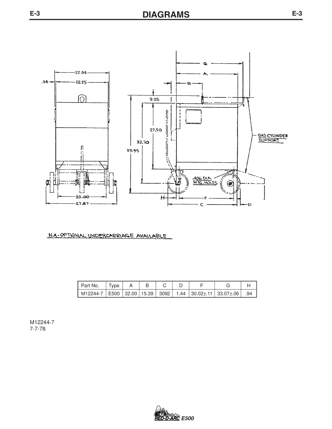
E-3
DIAGRAMS
E-3
Part No.
Type
A
B
C
D
F
G
H
M12244-7
E500
32.00
15.39
3092
1.44
30.02±.11
33.07±.06
.94
M12244-7
7-7-78
E500
Page 22
Page 24
Page 23
Image 23
Page 22
Page 24
Contents
RED-D-ARC E500
California Proposition 65 Warnings
Safety
Electric Shock can kill
Cylinder may explode if damaged
Précautions DE Sûreté
Thank You
Table of Contents
Output Studs
Installation
Input Wiring
Output Connections
Optional Equipment
Operation
Testing the Gfci Receptacle
Maintenance
General Maintenance
Power Rectifier Replacement
HOW to USE Troubleshooting Guide
Troubleshooting
Recommended
Symptoms Course of Action
Troubleshooting
Troubleshooting
Troubleshooting
Gfci
OCV is Rated OCV but
Checking Snubber Circuit
Procedure for Replacing P.C. Board
Output Voltage
Overload Protection
Power Silicon Controlled Rectifier Test
Toggle Switch Check
Remote Control Check
Checking Power Rectifier Bridge Assembly
SCR Test
Battery Test
Diagram
E500 Wiring Diagram 230/460/575
Wiring Diagram Code 10649 only
E500 Wiring Diagram 230/460/575
Wiring Diagram Code 11042 & UP
Diagrams
E500
E500
Precaucion
Aviso DE