TROUBLESHOOTING | ||
|
|
|
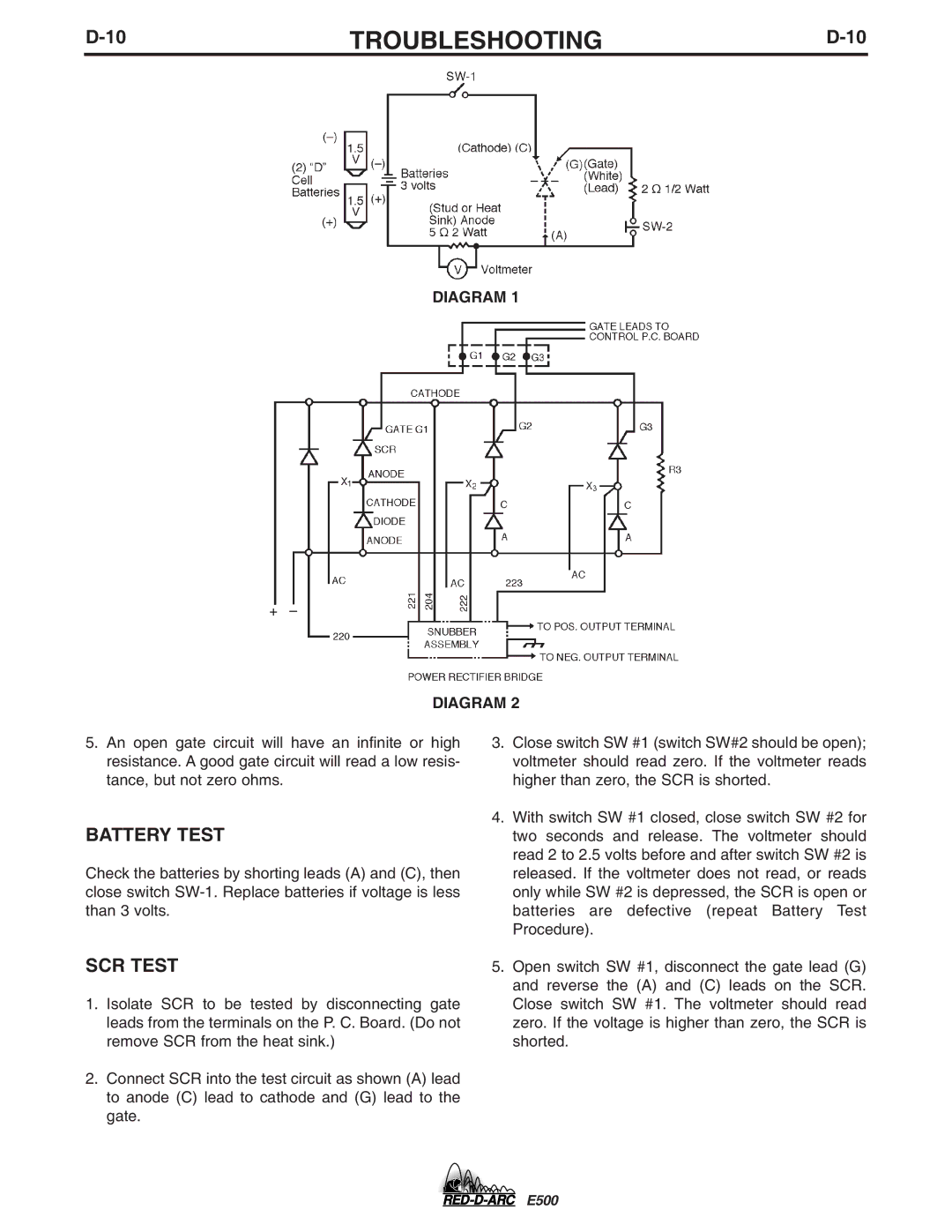
DIAGRAM 1
DIAGRAM 2
5.An open gate circuit will have an infinite or high resistance. A good gate circuit will read a low resis- tance, but not zero ohms.
BATTERY TEST
Check the batteries by shorting leads (A) and (C), then close switch
SCR TEST
1.Isolate SCR to be tested by disconnecting gate leads from the terminals on the P. C. Board. (Do not remove SCR from the heat sink.)
2.Connect SCR into the test circuit as shown (A) lead to anode (C) lead to cathode and (G) lead to the gate.
3.Close switch SW #1 (switch SW#2 should be open); voltmeter should read zero. If the voltmeter reads higher than zero, the SCR is shorted.
4.With switch SW #1 closed, close switch SW #2 for two seconds and release. The voltmeter should read 2 to 2.5 volts before and after switch SW #2 is released. If the voltmeter does not read, or reads only while SW #2 is depressed, the SCR is open or batteries are defective (repeat Battery Test Procedure).
5.Open switch SW #1, disconnect the gate lead (G) and reverse the (A) and (C) leads on the SCR. Close switch SW #1. The voltmeter should read zero. If the voltage is higher than zero, the SCR is shorted.
E500